
Compare: Gate valve vs globe valve — difference, when to use each & cross-section · Ball valve vs gate valve — difference, when to use each
For a complete guide to industrial valve types, visit the Industrial Valve Types Overview page.
1. Working Principle
Basic Operating Mechanism
A gate valve controls fluid flow by translating a flat or wedge-shaped gate element perpendicular to the pipe flow axis — raising the gate completely out of the flow path to open, and lowering it until the gate faces compress against opposing body seats to close. This linear motion is the defining mechanical characteristic of the gate valve: unlike the 90° quarter-turn of a ball or butterfly valve, the gate valve requires multiple full rotations of the handwheel or actuator to travel from fully closed to fully open — typically 5 to 30 complete stem rotations depending on bore size and stem thread pitch.
The stem connects the gate to the external actuating mechanism — handwheel, bevel gear operator, electric multi-turn actuator, or hydraulic linear actuator. In a rising stem design, the stem translates upward with the gate as it opens, providing visible external indication of valve position — the stem protrusion above the gland shows whether the valve is open or closed. In a non-rising stem design, the stem rotates in place while a threaded connection within the gate translates the gate without stem travel — used where overhead clearance is limited. For system-level valve selection strategy across all valve types, see How to Select an Industrial Valve. For the flow coefficient sizing methodology that determines the correct bore size for your gate valve application, visit Cv Value Explained.
Operating Physics and Flow Behavior
The gate valve’s flow behavior follows directly from its closure element geometry. When the gate is fully retracted into the bonnet cavity, the valve bore is completely clear — no part of the gate, seat ring, or stem intrudes into the flow path. This true full-bore passage is the gate valve’s defining flow performance advantage:
- Fully open pressure drop: With the bore completely clear, the gate valve’s resistance coefficient K is among the lowest of any isolation valve type — typically K = 0.1–0.3 for standard wedge gate valves. This corresponds to a fully-open Cv that approaches the equivalent straight pipe section, producing negligible pressure drop at normal pipeline velocities. For pipeline operators where every bar of pressure drop represents compressor fuel cost or throughput capacity, the gate valve’s nearly zero open-position pressure drop is its primary engineering advantage over globe valves (K = 3–10) in high-flow services.
- Pipeline pigging compatibility: The gate valve’s full-bore geometry — with the gate retracted entirely out of the pipe bore — allows pipeline inspection gauges (PIGs), cleaning pigs, and intelligent inspection tools to pass through the open valve without any restriction or protrusion that could obstruct or damage the tool. This full-bore pass-through is an absolute requirement for pipeline segments subject to periodic pigging, and it is the primary reason gate valves remain specified in pipeline service where ball valves are otherwise preferred.
- Wedge compression sealing mechanism: In the fully closed position, the gate descends until the angled faces of the gate contact both the upstream and downstream seat rings simultaneously. Continued stem force after contact compresses the gate between the two seats, generating a contact stress that seals against the operating pressure. The compression force has two components: the mechanical force applied by the stem through the handwheel or actuator, and the hydraulic force from the upstream line pressure acting on the upstream face of the closed gate, pushing the gate harder against the downstream seat. This pressure-assisted sealing means that the gate valve’s downstream seat leakage resistance improves with increasing upstream pressure — a self-reinforcing characteristic beneficial for high-pressure shut-in conditions.
- Behavior at partial opening — why throttling is prohibited: When the gate is in a partially open position, the flow path is a narrow crescent-shaped annular gap between the bottom edge of the gate and the valve bore. The flow velocity through this restricted gap is proportional to the full-flow velocity divided by the ratio of the gap area to the bore area. At 10% opening, the gap area is approximately 10% of the bore area, producing a flow velocity approximately 10× higher than the fully-open pipeline velocity. This very high velocity jet impinging on the gate face, body walls, and seat surfaces produces rapid erosion — both metal loss from abrasive particle impact and electrochemical corrosion from the turbulent flow field. Gate valves operated in partially open position in service develop visible seat and gate face erosion within weeks, producing leakage and loss of shutoff capability. The gate valve must be operated strictly in the fully open or fully closed position at all times in service.
- Water hammer risk on rapid closure: Multi-turn actuation produces inherently slow closing speed — typically 15–60 seconds for manual or motorized operation — which provides a natural mitigation against water hammer (pressure surge) in liquid pipelines. This slow closing characteristic, while a disadvantage for emergency shutdown response time, reduces the pressure surge that would be generated by rapid closure and protects upstream piping and equipment from hydraulic shock loads.
2. Structural Diagram and Anatomy
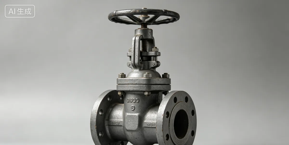
Component Breakdown
A gate valve is composed of the following primary structural components, each with defined engineering function and material requirements:
- Valve body: The primary pressure-retaining casting or forging providing inlet and outlet end connections and the internal cavity that guides the gate’s travel from the fully open (gate in bonnet) to fully closed (gate between seats) position. Gate valve body materials are selected based on the ASME B16.34 pressure class at design temperature, sour service NACE MR0175 hardness limits, and fluid chemical compatibility. Standard body materials include ASTM A216 WCB (carbon steel, general service), ASTM A217 WC6 (1.25Cr-0.5Mo low-alloy for elevated temperature to approximately 590°C), ASTM A217 WC9 (2.25Cr-1Mo for high-temperature steam to approximately 620°C), ASTM A217 C12A (9Cr-1Mo for power generation above 565°C), and ASTM A351 CF8M (316 stainless for corrosive service). The body casting integrates the seat ring pockets and the bonnet flange face that seals the bonnet-to-body joint.
- Bonnet: The upper body closure through which the stem passes, forming the upper pressure boundary of the valve. In bolted bonnet designs (standard for Class 150 through Class 600), the bonnet is a separate casting bolted to the body through a raised or ring-joint flange face with a gasket providing the pressure seal. In pressure-seal bonnet designs (standard for Class 900 through Class 2500), the bonnet is retained by a retaining ring and the sealing is provided by a pressure-energized seal ring — as internal pressure increases, the seal ring is compressed harder against the bonnet and body sealing faces, providing superior sealing performance at high pressure compared to the bolted bonnet arrangement whose bolt pre-load must resist the full blowout force of the operating pressure. Pressure-seal bonnets are the defining structural feature of high-pressure gate valves in power generation and refinery service.
- Gate (disc): The closure element that translates between the open and closed positions. Gate designs include:
- Solid wedge: A single-piece solid gate with angled seating faces that match the body seat ring angles. The most robust and simple gate design — preferred for general service, steam, and services with entrained solids where a flexible gate could be damaged by particle impingement.
- Flexible wedge: A solid gate with a circumferential machined groove that provides slight flexural compliance, allowing the gate faces to self-align to minor seat ring misalignment caused by thermal distortion of the body at elevated temperature. Preferred for high-temperature service where thermal cycling causes differential expansion between the gate and body that would cause the solid wedge to bind.
- Split wedge (double disc parallel seat): Two separate gate halves with a spreader mechanism between them. Each gate half self-aligns independently to its seat ring, providing superior sealing performance for applications with seat ring misalignment or body distortion. Used in dirty service and in services with corrosive fluids that may cause body distortion over time.
- Parallel slide: Two parallel-face gate discs separated by a spring — no wedging action. Closing force is provided by line pressure acting on the upstream disc. Preferred for steam service above 450°C where the parallel slide eliminates the risk of the gate sticking in the body due to thermal expansion, which is a known failure mode of wedge gate valves in severe thermal cycling service.
- Seat rings: The precision-machined sealing surfaces in the valve body that contact the gate faces in the closed position. In smaller bore and lower pressure class designs, the seats are integral — machined directly into the valve body casting. In larger bore and higher pressure class designs, the seats are removable inserted rings — threaded, pressed, or welded into the body seat pockets — allowing seat replacement in-situ without removing the valve from the pipeline. Seat ring material must be compatible with the process fluid and must provide adequate surface hardness to resist the relative motion between the gate face and seat ring during cycling. Stellite (cobalt-chromium alloy, hardness 38–45 HRC) hardfacing is standard for high-temperature steam and refinery gate valves, providing excellent galling resistance and wear life.
- Stem and stem thread: The torque-to-thrust conversion element that translates the actuator’s rotational input into the gate’s linear displacement. The stem thread — an Acme or modified square thread with low friction and self-locking geometry — provides the mechanical advantage that allows the actuator’s torque to generate the high gate closure force required for positive sealing. Stem materials must resist the torsional stress of actuation and the tensile stress from differential pressure on the closed gate — typically ASTM A182 F316 stainless steel for corrosive service, or 17-4 PH stainless steel for high-strength applications.
- Stem packing and gland: The dynamic sealing system between the rising or rotating stem and the bonnet stem bore. Flexible graphite braided packing rings are standard for high-temperature steam and process service — graphite retains its sealing performance and flexibility above 500°C, unlike PTFE or elastomeric packings that are thermally excluded above 250°C. The gland follower is bolted to the bonnet and pre-loads the packing rings to the required compression. Live-loaded packing glands — with spring washers maintaining constant packing compression — are used in services where thermal cycling causes repeated packing consolidation and leakage, eliminating the need for frequent manual gland adjustment.
Structure Diagram Explanation
Tracing the flow path and mechanical assembly of a rising stem solid wedge gate valve from bottom to top: the valve body provides the horizontal flow channel with the seat ring pockets on the upstream and downstream sides of the body cavity. The wedge gate hangs in the body cavity between the two seat rings, guided by machined guide ribs on the body interior that prevent lateral movement of the gate during travel. The stem threads into a tapped hole in the top of the gate (inside stem thread design) or engages the gate through a T-head connection (outside stem thread design). The stem passes upward through the bonnet bore and the packing gland, with the packing rings compressed between the gland follower and a packing box machined into the bonnet bore. The handwheel or actuator mounts to the stem above the gland on an integral yoke that transmits the reaction force from stem rotation to the bonnet structure.
Opening the valve by rotating the handwheel counterclockwise (standard convention) causes the stem to rotate, and the stem thread engagement with the gate converts this rotation to upward gate translation — the gate rises out of the flow bore into the bonnet cavity, progressively increasing the flow area until the gate clears the bore completely at full open. Closing reverses this sequence — clockwise rotation lowers the gate into the bore and ultimately compresses it between the seat rings. The rising stem’s visible position above the gland provides unambiguous visual confirmation of valve open or closed status — a safety feature valued in manual valve applications where instrument position indication is not available.
3. Advantages and Disadvantages
Engineering Advantages
Gate valves offer a specific set of engineering advantages that make them the preferred or required choice in their optimal application domain:
- True full-bore passage — pipeline pigging capability: When fully open, the gate retracts completely into the bonnet cavity, leaving the pipeline bore entirely clear. No part of the valve mechanism intrudes into the flow path. This full-bore clearance is the gate valve’s defining functional advantage over all rotary valve types — butterfly, ball (reduced bore), and plug valves all have some intrusion into the flow path even when fully open. For pipeline systems requiring periodic pigging, the gate valve’s full-bore geometry is frequently a specification requirement that cannot be substituted.
- Lowest fully-open pressure drop for non-ball designs: With the gate fully retracted, the pressure drop through a gate valve is governed only by the minor turbulence from the flow entering and exiting the body cavity. Resistance coefficient K = 0.1–0.3 for standard wedge gate valves in the fully open position — significantly lower than globe valves (K = 3–10) and comparable to reduced-bore ball valves. For high-flow, large-bore services where minimizing fully-open pressure drop is critical to system throughput, the gate valve competes favorably with reduced-bore ball valve designs on pressure drop performance.
- Superior high-temperature performance in pressure-seal bonnet designs: Pressure-seal bonnet gate valves (Class 900 and above) are specifically engineered for high-temperature steam and process gas service where bolted flange connections would require periodic bolt re-torquing due to creep relaxation of gaskets and bolts at sustained elevated temperature. The pressure-seal bonnet’s self-energizing seal geometry eliminates this maintenance requirement — as steam pressure acts on the bonnet, it compresses the seal ring harder, maintaining seal integrity without external bolt pre-load. This characteristic makes the pressure-seal bonnet gate valve the standard choice for main steam isolation in power generation plants.
- Robust construction for high-pressure, high-temperature service: Gate valve bodies in alloy steel (WC6, WC9, C12A) for Class 900 through Class 2500 high-temperature service represent the most extensively proven valve design in power generation and refinery applications. Their simple, compact pressure boundary geometry — without the large body cavity and trunnion bearing complexity of an equivalent trunnion ball valve — provides reliable long-term performance in the most demanding thermal cycling service conditions.
- Bidirectional flow capability: Standard gate valve designs are symmetric — they seal with equal effectiveness regardless of which side is the high-pressure side. This bidirectional capability eliminates the need to specify flow direction during installation — the valve performs correctly in either orientation in the pipeline.
Engineering Limitations and Drawbacks
Gate valves have well-defined limitations that must be recognized and respected in application engineering to avoid premature failure and maintenance problems:
- Multi-turn slow actuation: The gate valve’s linear-motion stem mechanism requires 5 to 30 complete stem rotations to travel from fully closed to fully open — a multi-turn actuation sequence that takes 15–60 seconds at manual or motorized operation speed. This slow response is fundamentally incompatible with Emergency Shutdown (ESD) valve applications where response time must be within 3–10 seconds of the shutdown signal. Gate valves cannot be specified for ESD or safety-critical fast-closure applications — quarter-turn ball valves with spring-return pneumatic or hydraulic actuators are required for fast-closure safety applications.
- Prohibited from throttling service: As detailed in the working principle section, gate valves operated in partially open position experience rapid erosion of the gate face and seat ring surfaces from the high-velocity crescent-shaped flow through the narrow gap. The resulting seat damage produces leakage and loss of shutoff capability within a short period of throttling service. Gate valves must be specified, installed, and operated strictly for fully open or fully closed service — never for intermediate positions.
- High installation height requirement: The gate valve bonnet must provide sufficient cavity height for the gate to retract entirely above the bore in the fully open position — requiring bonnet height approximately equal to the full bore diameter above the body flange face. A 12-inch gate valve in Class 1500 has a total installation height (bottom of body to top of handwheel) of approximately 1,500–2,000 mm — significantly more than an equivalent ball valve or butterfly valve. This height requirement creates installation space constraints in pipe racks with limited vertical clearance between pipe supports.
- Gate wedge binding in thermal cycling: Solid wedge gate valves in high-temperature service can experience gate binding — the gate becomes mechanically locked in the body between the seat rings due to differential thermal expansion when the valve cools from operating temperature to ambient. The steel body cools faster than the heavier gate, contracting around the wedge gate and clamping it in position. This thermal binding produces extreme difficulty in opening the valve after a plant shutdown — requiring high manual effort or powered actuation that may exceed normal operator capability. Flexible wedge and parallel slide gate designs mitigate this issue through compliance and non-wedging geometry respectively.
- Seat wear in cycling service: Each open-close cycle of a gate valve involves the gate face sliding against the seat ring surface as the gate contacts and retracts from the seats. This sliding motion produces progressive wear of both the gate face hardfacing and the seat ring hardfacing, reducing the height of the sealing surface and eventually producing leakage. In services requiring frequent cycling — more than 500–1,000 cycles per year — this seat wear accelerates to the point where seat reconditioning (in-situ grinding and lapping) is required at intervals shorter than the design maintenance period.
4. Industrial Applications and Use Cases
Common Industrial Sectors
Gate valves serve specific, well-defined applications across major industrial sectors where their full-bore geometry, low pressure drop, and high-temperature pressure-seal bonnet design provide performance that alternative valve types cannot match:
- Power Generation — Main Steam and High-Temperature Service: Pressure-seal bonnet gate valves in alloy steel (ASTM A217 WC9 for 2.25Cr-1Mo, or C12A for 9Cr-1Mo) are the standard valve type for main steam isolation, turbine bypass, feedwater, and extraction steam services in thermal power plants. These services operate at steam temperatures of 540–600°C and pressures of 250–350 bar in modern ultra-supercritical units — conditions that represent the most thermally demanding service environment in industrial valve applications. The gate valve’s pressure-seal bonnet provides the self-sealing geometry required for sustained reliable operation at these conditions without the routine maintenance that bolted bonnet designs would demand at elevated temperature. For comparison with ball valve design in moderate-temperature power plant service, see Ball Valve.
- Oil and Gas Pipeline — Large Bore, Low-Frequency Isolation: Gate valves serve large-bore mainline block isolation in older pipeline systems and in applications where full-bore pigging access is required but the procurement cost and weight of a full-bore trunnion ball valve is uneconomical. Slab gate valves — with a flat parallel-slide gate rather than a wedge — are used in high-pressure natural gas transmission systems because their smooth gate geometry is fully compatible with pipeline pigging. For comparison with the preferred modern alternative for pipeline isolation, see Plug Valve.
- Petrochemical and Refinery — High-Temperature Process Isolation: Gate valves in alloy steel body with Stellite-hardfaced seats and gates serve isolation service in catalytic cracking units, hydrocracking units, and high-temperature reforming units where sustained temperatures above 350°C and process pressures above 100 bar demand the proven alloy steel-and-stellite construction that the gate valve design accommodates. In these applications, the gate valve’s simple body geometry — without the complex trunnion bearing and seat spring system of a trunnion ball valve — provides lower maintenance complexity for high-temperature service.
- Water and Wastewater Treatment — Large Bore Distribution: Gate valves in ductile iron or cast iron body with resilient EPDM or NBR seat liners serve large-bore water main isolation in distribution networks. The resilient-seat gate valve (with a rubber-coated gate that seals against a smooth seat ring) provides reliable zero-leakage shutoff for water service at moderate pressures (Class 150, typically below 20 bar), and is a cost-effective alternative to butterfly valves in bore sizes of 4 to 24 inches in buried pipeline applications where access for butterfly valve disc inspection is limited.
- Chemical Processing — Full-Bore Chemical Isolation: Gate valves in stainless steel (CF8M) or high-alloy body provide full-bore isolation in chemical process lines where the full-bore passage is required for cleaning or inspection and where ball valves are not suitable due to cavity trapping of chemical deposits. In chemical slurry service, knife gate valves — a thin-gate design specialized for cutting through thick fluids, slurries, and fibrous materials — provide isolation capability that standard wedge gate or ball valve designs cannot achieve in high-viscosity or entrained-solids service.
Typical Engineering Scenarios
The following worked scenarios illustrate how gate valve design parameters are derived from service conditions:
- High-temperature refinery isolation (150 bar, 250°C, sour gas H₂S service, 10-inch): Gate valve, ASTM A217 WC6 (1.25Cr-0.5Mo) body with NACE MR0175 hardness certification (body hardness ≤22 HRC throughout all pressure-retaining sections), Stellite 6 weld overlay on gate face and seat ring seating surfaces — noting that Stellite 6 at 38–45 HRC may require individual qualification under NACE MR0175 Part 3 Clause 3 for cobalt-base alloys in sour service, or alternative Inconel 625 overlay for NACE-compliant metal seat at full hardness. Bolted bonnet design with spiral wound graphite gasket at 250°C — pressure-seal bonnet required above approximately Class 600 at this temperature. Pressure class confirmed from ASME B16.34 Group 1.2 P-T table at 250°C for WC6 material. For systematic pressure class determination at operating temperature, refer to Pressure Class Selection.
- Ultra-supercritical power plant main steam isolation (280 bar, 600°C, steam, 16-inch): Gate valve, ASTM A217 C12A (9Cr-1Mo Grade 91) body, pressure-seal bonnet with high-temperature alloy seal ring, Stellite-hardfaced integral seat rings, parallel slide gate design to prevent thermal binding, electric multi-turn actuator with torque limiter. At 600°C, ASME B16.34 Group 1.10 (Grade 91 material) rated pressure must be confirmed — Grade 91 retains significantly higher allowable stress at 600°C than carbon or low-alloy steels, enabling Class 2500 operation at this temperature. For temperature-dependent material selection guidance, refer to Temperature Rating.
- Pipeline pig receiver inlet isolation (100 bar, 50°C, natural gas, 20-inch full bore): Slab gate valve (parallel slide, full bore), ASTM A216 WCB carbon steel body, Class 600, PTFE-injected sealant system for resilient seating in the intermediate shut-in position, fire-safe design per API 6D. The slab gate’s flat parallel-face geometry provides unobstructed full-bore passage in the open position — allowing pipeline pigs to pass — and seals by line pressure acting on the upstream gate disc to push it against the downstream seat. For the comparison with ball valve design for the same service, including the DBB isolation capability consideration, refer to Floating vs Trunnion Selection.
5. Relevant Standards and Codes
Applicable International Standards
Gate valves for industrial service are governed by the following primary international standards, each covering distinct aspects of design, material, dimensional, and testing requirements:
- API 600 — Bolted Bonnet Steel Gate Valves for Petroleum and Natural Gas Industries: The primary standard for bolted bonnet and pressure-seal bonnet steel gate valves in oil and gas and petrochemical service. API 600 specifies body wall minimum thickness for Class 150 through Class 2500, seat ring design and material requirements (integral or inserted, with Stellite or equivalent hardfacing), gate design types (solid wedge, flexible wedge, split wedge, parallel slide), stem design (rising versus non-rising, inside versus outside stem thread), packing box dimensions, and bonnet-to-body joint design. API 600 also mandates blow-out proof stem design and anti-static provisions for hydrocarbon service, and requires that the drive train — stem, stem nut, and actuator mounting — be capable of generating the required gate seating force with an adequate safety margin above the calculated minimum seating load.
- API 6D — Specification for Pipeline and Piping Valves: API 6D governs gate valves specifically in oil and gas pipeline service, covering full-bore and reduced-bore designs, fire-safe qualification requirements (API 607 and API 6FA), slab gate valve designs for pigging applications, and the specific bore geometry requirements (full bore ≥ 95% of nominal pipe inside diameter) that ensure pig compatibility. API 6D requires shell hydrostatic test at 1.5× rated pressure, low-pressure gas seat test, and high-pressure liquid seat test for all covered gate valves, with zero leakage required for soft-seated designs.
- ASME B16.34 — Valves: Flanged, Threaded, and Welding End: Provides the pressure-temperature rating tables for all gate valve body materials in all pressure classes from Class 150 through Class 4500. The P-T rated pressure at design temperature — from the applicable material group table — is the governing structural limit for gate valve body design. At high operating temperatures, the temperature derating of carbon and low-alloy steels is significant: a Class 900 WCB carbon steel gate valve body has a rated pressure of approximately 153 bar at ambient temperature, reducing to approximately 137 bar at 250°C and approximately 100 bar at 400°C. For high-temperature services above 400°C, the P-T ratings for alloy steels (WC6, WC9, C12A) must be confirmed — Grade 91 (C12A) provides approximately 138 bar at 600°C in Class 2500, enabling ultra-supercritical steam applications that carbon steel cannot serve.
- API 598 — Valve Inspection and Testing: Specifies factory acceptance test requirements for gate valves: shell hydrostatic test at 1.5× rated pressure (60 seconds minimum); backseat test (stem packing gland fully loosened, valve fully opened, body pressurized — confirms the backseat seating ring seals the stem bore when the valve is fully open, allowing packing replacement under pressure); and closure test (liquid seat test — zero leakage for soft-seated designs; maximum 6 drops per minute per API 598 Table 4 for metal-seated designs in NPS ≤ 2, and maximum 9 drops per minute for NPS 2.5–8, with higher allowances for larger bore sizes). These acceptance criteria are quantitative pass/fail thresholds that must be referenced in every gate valve purchase specification.
- ASME B16.10 — Face-to-Face and End-to-End Dimensions of Valves: Standardizes the face-to-face dimensions for all gate valve pressure classes and bore sizes with flanged, butt-welding, and threaded end connections. ASME B16.10 compliance ensures that a gate valve from any manufacturer can be replaced in-line by any other compliant gate valve of the same bore and pressure class without requiring pipe modifications — a critical maintainability requirement for installed systems.
How These Standards Affect Design and Selection
The combined effect of the applicable standards on gate valve specification and engineering decision-making is to define every quantifiable performance parameter that a gate valve must meet before it can be specified for a given service:
- Pressure class confirmation at design temperature: ASME B16.34 P-T tables force confirmation of the gate valve’s rated pressure at the actual design temperature — not at ambient. This is particularly critical for gate valves in high-temperature steam and refinery service, where temperature derating is large and where the difference between ambient-temperature class rating and the rating at design temperature may require upgrade to a higher pressure class or a higher-alloy body material.
- Stem and gate seating force adequacy: API 600 and API 6D require that the valve be designed and tested to demonstrate that the available actuating mechanism (handwheel or powered actuator) can generate the minimum required gate seating force — the compressive load on the seats required to achieve the specified leakage class — at maximum design differential pressure, after accounting for packing friction, gate weight, and stem thread efficiency. This requirement forces the actuator sizing calculation to be performed during design rather than discovered as inadequate during commissioning.
- Factory test documentation traceability: API 598 shell and closure test records — including test medium, test pressure, test duration, and measured leakage (if any) — must accompany every gate valve as part of the quality documentation package. Valve data books must include the test certificate with the specific valve serial number and test date, traceable to the individual valve tested. Valves without complete, individually traceable test documentation must not be accepted at goods receipt.
- Seat hardfacing qualification for sour service: NACE MR0175/ISO 15156 hardness limits for sour service (H₂S above threshold partial pressure) apply to all wetted metallic components — including seat ring hardfacing and gate face hardfacing. Standard Stellite 6 hardfacing at 38–45 HRC exceeds the NACE 22 HRC limit and requires individual qualification under NACE MR0175 Part 3 for cobalt-base alloy overlays, or substitution with NACE-compliant Inconel 625 overlay. This qualification must be explicitly required in the purchase specification for all gate valves in sour service.
6. Related Valve Types and Internal Linking
Gate valves occupy a specific and well-defined application niche within the industrial valve landscape — primarily full-bore isolation in high-temperature service and pipeline pigging applications. For each application where a gate valve is under consideration, the following related valve type pages provide the engineering basis for comparing the gate valve against alternative designs. Use them in conjunction with the valve selection module to confirm that a gate valve is the optimum type for your specific service conditions, or to identify the cases where a ball valve, globe valve, or butterfly valve would provide superior performance:
- Industrial Valve Types Overview — The complete engineering summary covering all valve types, working principles, structural anatomy, comparative advantages, and applicable standards
- Ball Valve — The primary modern alternative to gate valves in on-off isolation service; quarter-turn, compact, fast-actuating, and available in full-bore configuration for pigging service; the preferred choice for automated ESD and high-frequency cycling applications
- Globe Valve — Linear motion valve for throttling and flow control service; provides the precise, stable Cv-versus-stroke characteristic that neither gate valves nor ball valves can achieve in modulating control applications
- Check Valve — Self-actuating non-return valve; typically installed in combination with gate valve isolation on pump and compressor discharge lines to prevent reverse flow during shutdown
- Butterfly Valve — Compact, lightweight quarter-turn disc valve; an alternative to gate valves in large-bore, low-to-moderate pressure services where gate valve installation height and weight are unacceptable and full-bore pigging access is not required
- Plug Valve — Quarter-turn rotary valve; slab gate valve alternative for pipeline pig-compatible isolation in moderate-pressure natural gas gathering systems
- Needle Valve — Precision low-flow throttling valve for instrument connections and sample lines; typically installed in series with a gate valve isolation upstream for safe maintenance access to instrument connections