
For a complete guide to industrial valve types, visit the Industrial Valve Types Overview page.
1. Working Principle
Basic Operating Mechanism
A check valve is a self-actuating, non-return valve that permits fluid flow in one direction only — the forward (design) flow direction — and automatically closes to prevent flow in the reverse direction. Unlike every other valve type covered in this cluster, the check valve requires no external actuation input, no operator action, and no control system signal to function. Its closure element — a disc, flap, ball, or piston depending on design type — responds directly and autonomously to the direction and magnitude of fluid flow: forward flow generates a net pressure force on the closure element in the opening direction, holding the valve open; reversal or cessation of flow generates a net force in the closing direction, seating the closure element against the seat ring and blocking reverse flow.
This automatic self-actuation is the check valve’s defining functional characteristic and its primary engineering value: it provides continuous, passive protection against reverse flow in pumping systems, compressor discharge lines, and pipeline networks without requiring any form of external energy, control signal, or operator awareness. The check valve’s response to flow reversal begins as soon as the forward flow velocity decreases to the point where the net pressure force on the disc changes direction — before significant reverse flow has actually occurred in well-designed installations. For system-level valve selection strategy across all valve types, see How to Select an Industrial Valve. For the flow coefficient framework that applies to fully-open check valve pressure drop calculation, visit Cv Value Explained.
Operating Physics and Flow Behavior
The opening and closing behavior of a check valve is governed by a force balance on the closure element at every instant of operation. Understanding this force balance is essential to predicting check valve performance — particularly the closing speed and the potential for water hammer:
- Opening force balance: In the forward flow direction, the upstream pressure P₁ acts on the upstream face of the closure element (area A_disc) and the downstream pressure P₂ acts on the downstream face. The net opening force is F_open = (P₁ − P₂) × A_disc = ΔP × A_disc. For the valve to be in the fully open position, this differential pressure force must exceed the sum of the spring pre-load force (if spring-loaded), the disc weight component (for designs where the disc has a gravitational component), and the friction in the hinge or guide mechanism. The minimum differential pressure required to hold the valve fully open — the cracking pressure — is therefore: ΔP_crack = (F_spring + F_gravity + F_friction) / A_disc. For spring-loaded designs, the spring pre-load is the dominant term; for gravity-operated swing check designs, disc weight is dominant.
- Closing force balance and closing speed: As forward flow decelerates — due to pump shutdown, valve closure upstream, or system pressure reversal — the differential pressure across the check valve disc decreases. When ΔP drops to zero (equal pressure on both sides), the only forces acting are the spring pre-load and disc weight component, both in the closing direction. The disc begins to move toward the seat. If the flow decelerates slowly enough that the disc reaches the seat before reverse flow velocity develops, the valve closes quietly with minimal hydraulic impact. If flow decelerates rapidly (rapid upstream valve closure or instantaneous pump trip), reverse flow may develop before the disc reaches the seat — the resulting reverse-flow disc slam generates a pressure wave (water hammer) whose magnitude is proportional to the reverse flow velocity at the moment of disc contact with the seat: ΔP_slam = ρ × a × V_reverse, where ρ is fluid density, a is acoustic velocity in the pipeline, and V_reverse is the reverse flow velocity at disc contact.
- Swing check disc dynamics: In a conventional swing check valve, the disc hangs from a hinge pin above the flow bore and swings open under forward flow. The disc’s angular momentum — a function of its mass, center of gravity position relative to the hinge, and angular velocity of opening — determines how quickly it responds to flow deceleration. Heavy, large-diameter swing check discs have high angular momentum and respond slowly to flow changes, making them susceptible to reverse-flow slam in systems with rapid pump trip. Lightweight dual-plate wafer check valves and spring-loaded axial-flow check valves have much lower closure inertia and respond faster to flow changes, closing before significant reverse flow develops even in rapid pump-trip scenarios.
- Axial-flow check valve — fastest closing design: In an axial-flow (nozzle-type) check valve, the closure element is a spring-loaded disc or piston that travels parallel to the flow axis — the same direction as the fluid flow. This geometry minimizes the disc travel distance for closure (typically 10–25 mm for a 4-inch axial check valve, versus 80–150 mm of disc swing arc for an equivalent swing check), and the spring provides a positive closing force that begins acting as soon as forward flow velocity decreases. The result is a closing speed 5–10 times faster than an equivalent swing check valve, virtually eliminating reverse-flow water hammer in pump discharge service. Axial-flow check valves are the required design for compressor discharge service and for pumping systems where system hydraulic analysis confirms unacceptable water hammer risk with conventional swing check designs.
- Cracking pressure and pressure drop: The cracking pressure — the minimum upstream-to-downstream differential pressure required to open the valve — is a key selection parameter. High cracking pressure (from high spring pre-load) reduces the risk of nuisance opening from minor pressure fluctuations but increases the energy consumed by the valve throughout its service life. Low cracking pressure minimizes energy loss but may cause the disc to chatter (rapidly open and close) under low-flow pulsating conditions, producing disc and seat wear. For pump discharge applications, the minimum cracking pressure must be confirmed to be lower than the differential pressure available from the pump at minimum flow — if the check valve cracking pressure exceeds the pump differential pressure at minimum flow, the pump cannot open the check valve and the pumping system cannot start.
2. Structural Diagram and Anatomy
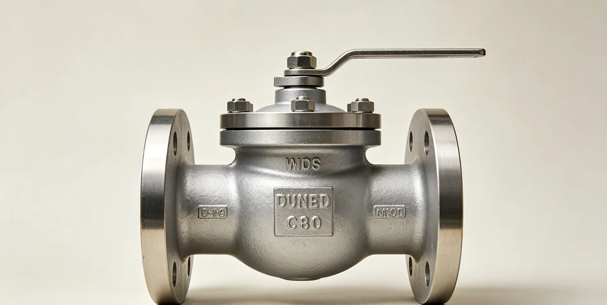
Component Breakdown
Check valves are available in several distinct design types — each with a different closure element geometry, body architecture, and installation orientation requirement. The following describes the components common to all designs and the type-specific distinctions:
- Valve body: The primary pressure-retaining casting or forging providing the flow bore, seat ring pocket, and the hinge or guide mechanism for the closure element. Body material selection follows the same ASME B16.34 material group and pressure class framework as all other valve types: ASTM A216 WCB for carbon steel general service, ASTM A351 CF8M for stainless service, and high-alloy castings for corrosive service. Check valve bodies are available in full-bore designs (where the flow bore through the valve equals the nominal pipeline bore) and reduced-bore designs (typically one bore size smaller than the pipeline nominal bore, acceptable where pipeline pigging is not required and the additional pressure drop can be tolerated). Body end connection types — flanged (ASME B16.5), butt-welding (ASME B16.25), wafer (clamped between pipeline flanges with no body flange), or lug (through-bolted lug body) — determine the installation requirements and maintenance access for the check valve in service.
- Disc (closure element): The moveable component that opens under forward flow and closes under reverse flow or flow cessation. Disc designs by check valve type:
- Swing check: A single circular disc hinged at the top of the body, swinging open (rotating about the hinge pin axis) under forward flow. The disc hangs by gravity in the closed position when no flow is present, providing passive closure without a spring. Swing check discs may be solid metal (for general service) or rubber-faced (for water service requiring tight shutoff).
- Dual-plate wafer check: Two semi-circular plates (halves of a split disc) connected by a central hinge pin, folded open in the center of the flow bore under forward flow and spring-returned to the flat closed position on flow cessation or reversal. The compact wafer body geometry and spring-return closing provide fast closure with minimal reverse flow — the primary advantage over swing check in pulsating or rapidly-cycling services.
- Lift check: A disc or ball that translates axially — lifts off the seat under forward flow differential pressure and drops back to the seat under gravity (vertical installation, disc lift) or spring force (horizontal installation, spring-loaded lift check). Lift checks are limited to clean fluids (no solids that could prevent the disc from reseating) and require specific installation orientation for gravity-operated designs.
- Axial-flow (nozzle) check: A spring-loaded disc or piston that translates parallel to the flow axis, compressing the spring to open and returning to the seat by spring force when forward flow decreases. The fastest closing design — preferred for compressor discharge and high-speed pump discharge service.
- Seat ring: The precision-machined sealing surface that the disc contacts in the closed position. Seat ring design and material selection follow the same principles as other valve types: soft seats (rubber, EPDM, NBR) for water and low-temperature service requiring zero-leakage Class VI shutoff; metal seats (Stellite or Inconel 625 hardfaced) for high-temperature, high-pressure, and fire-safe service. Seat rings in check valves are subject to the impact energy of disc closure — particularly in swing check and ball-type designs where the closure element has significant momentum at the moment of seat contact. Seat ring face geometry must be matched to the disc face geometry to distribute this impact load without yielding the seat material or cracking the disc insert.
- Hinge pin and arm (swing check): The pivot mechanism about which the swing check disc rotates. The hinge pin must be sized to withstand the combined bending load from disc weight and the differential pressure force on the disc at maximum operating pressure — the bending stress in the hinge pin at maximum differential pressure is the governing structural load in the swing check hinge design. Hinge arm length (distance from hinge pin to disc center) determines the mechanical advantage and the disc angular momentum during closure — longer arm length reduces closing speed and increases water hammer risk.
- Return spring (spring-loaded designs): The compression spring that provides the positive closing force in spring-loaded lift check, dual-plate wafer check, and axial-flow check valves. Spring material must be compatible with the process fluid chemistry and temperature — standard springs in 316 stainless steel are suitable for most process services; Inconel 718 springs are required for high-temperature steam and corrosive service above the 316SS temperature limit. Spring pre-load (the compression force at the fully closed position) determines the cracking pressure and the initial closing force available when forward flow begins to decelerate.
- Body drain and inspection ports: Full-bore check valve bodies in larger bore sizes typically include a bottom drain connection for flushing the body cavity and a top inspection cover for in-service disc and seat inspection without removing the valve from the pipeline. The inspection cover is a bolted flat-face flange on the top of the body, sized to allow the disc assembly to be withdrawn vertically for inspection and seat reconditioning.
Structure Diagram Explanation
Tracing the flow path and closure mechanism of a swing check valve: fluid enters the inlet port horizontally, impinges on the disc face, and generates a differential pressure force that rotates the disc upward about the hinge pin — opening the valve and allowing forward flow to pass through the body bore to the outlet. When forward flow stops, the disc swings back down under gravity (or spring force), rotating toward the seat ring. If reverse flow develops before the disc reaches the seat, the reverse-flow velocity generates an additional closing force that accelerates the disc toward the seat — but also means that significant reverse flow has already passed through the valve. The disc contacts the seat ring at some reverse flow velocity, generating the water hammer pressure spike that propagates upstream.
For maintenance access, the swing check body’s top inspection cover is removed after depressurizing and draining the valve — the disc and hinge arm assembly can then be lifted out vertically for inspection of the disc face and hinge pin bearing. Seat ring condition is inspected through the open body top. In-situ seat ring reconditioning (lapping) can be performed with the valve in the line after removing the disc assembly, using a hand lapping tool guided by the seat ring bore. Full seat ring replacement requires body removal from the line in welded-seat designs, or in-situ seat ring removal in threaded-insert designs.
3. Advantages and Disadvantages
Engineering Advantages
Check valves provide a specific set of engineering performance characteristics that make them an essential and irreplaceable component in virtually every pumping, compression, and pipeline system:
- Fully automatic operation — no external energy or control required: The check valve operates entirely from the fluid’s own energy — no instrument air, electrical power, control signal, operator presence, or external actuation mechanism is required. This passive self-actuation makes check valves the most reliable protection mechanism against reverse flow: they cannot fail to close due to loss of instrument air (as a fail-safe actuated ball valve could), control system failure (as an automated valve could), or operator error (as a manually-operated valve could). In a system failure scenario — pump trip, power loss, upstream valve failure — the check valve closes automatically and immediately without depending on any other system element.
- Positive pump and compressor protection: Check valves on pump and compressor discharge lines prevent reverse rotation — the reverse flow that would occur through an unprotected pump after shutdown would drive the pump impeller in the reverse direction, potentially causing mechanical damage to the pump seal, bearing, or impeller, or in the case of some pump types, causing the pump to run in reverse as a turbine and accelerate to damaging speeds. The check valve prevents this reverse flow from reaching the pump, limiting reverse rotation to the coastdown of the pump’s own inertia.
- Backflow contamination prevention: In water supply, pharmaceutical, and food processing systems, check valves prevent potentially contaminated fluid from flowing backward into the clean supply line — a critical public health protection function in potable water distribution systems and process sanitary piping.
- Simple, low-maintenance construction: Most check valve designs — particularly swing check and dual-plate wafer check types — have only one or two moving parts (disc, hinge pin, and spring), minimal sealing surfaces (disc-to-seat contact only, no stem packing), and no actuating mechanism to maintain. In clean service, check valves can operate indefinitely between maintenance interventions, requiring only periodic disc and seat inspection at major maintenance shutdowns.
- Wide pressure class and temperature range availability: Check valves are available across the full ASME B16.34 pressure class range from Class 150 through Class 4500, in bore sizes from NPS ½ through NPS 60 and larger, and in body materials covering the full spectrum from ductile iron and carbon steel through high-nickel alloys for cryogenic and high-temperature service.
Engineering Limitations and Drawbacks
Check valves have specific limitations that must be recognized and managed in the system design and maintenance program:
- Water hammer on disc slam: In systems with rapid flow deceleration — fast pump trip, quick upstream valve closure, or sudden system pressure reversal — swing check and lift check valves may not close before reverse flow develops, resulting in disc slam and the associated water hammer pressure spike. The magnitude of the water hammer pressure spike can reach several times the normal operating pressure in severe cases, threatening pipeline integrity, flange gasket sealing, and connected equipment. For high-risk systems (high pipeline velocity, long pipeline length downstream of the pump, multiple pumps operating in parallel), a transient hydraulic analysis must be performed to quantify the water hammer risk and specify the required check valve type (dual-plate or axial-flow with spring return) to achieve closure before reverse flow develops.
- Disc chatter in low-flow or pulsating service: If the system flow rate is near the minimum flow required to hold the check valve disc fully open — near the cracking pressure condition — the disc oscillates between partially open and partially closed positions at the frequency of any flow pulsation in the system. This disc chatter produces repetitive impact loads on the disc face, seat ring, and hinge pin, causing rapid wear and premature failure of all three components. Disc chatter must be prevented by ensuring that the normal operating flow rate holds the disc stably open — typically at least 30–50% above the cracking pressure flow rate — and by selecting spring-loaded designs with positive snap-open characteristics for pulsating flow applications such as reciprocating compressor discharge service.
- Solids and fouling vulnerability: Swing check and lift check valves are vulnerable to solid particle deposition on the seat ring and between the disc and seat that prevents full closure, causing leakage in the reverse-flow direction. In water systems with suspended solids, chemical precipitation service, or any service producing scale or deposit formation, check valve seat fouling is a chronic maintenance issue requiring frequent inspection and cleaning. Wafer dual-plate designs with their flat disc geometry are somewhat less vulnerable to fouling than the recessed-seat designs of some swing check configurations.
- No flow control or isolation capability: A check valve provides only one function — passive non-return protection. It cannot be used to isolate the pipeline for maintenance, nor can it throttle or regulate flow rate. Every check valve installation must be accompanied by an isolation valve upstream and downstream for maintenance isolation. The check valve provides no contribution to the system’s isolation or flow control capability.
- Installation orientation restrictions: Gravity-operated swing check and lift check valves have defined required installation orientations — horizontal pipeline for swing check (with hinge pin horizontal), or vertical upward flow for vertical lift check. Installing a gravity-operated check valve in the wrong orientation prevents the disc from closing by gravity and eliminates the valve’s non-return function. Spring-loaded designs (dual-plate, axial-flow) can be installed in any orientation including vertical downward flow, providing installation flexibility that gravity-operated designs cannot.
4. Industrial Applications and Use Cases
Common Industrial Sectors
Check valves are installed in virtually every industrial process and utility system that contains a pump, compressor, or any flow path where reverse flow would cause damage, contamination, or safety risk. The following describes the primary application domains and the specific check valve design considerations for each:
- Oil and Gas — Pump and Compressor Protection: Check valves on pump discharge lines in oil and gas production facilities — crude oil transfer pumps, injection water pumps, chemical injection pumps, and gas lift compressor discharge — prevent reverse rotation and reverse flow through pumps and compressors on shutdown. In multi-pump parallel configurations, check valves on each pump’s discharge prevent the operating pump(s) from forcing reverse flow through the stopped pump — a condition that would cause the stopped pump to spin backward and potentially damage the mechanical seal. Full-bore swing check valves in API 6D carbon steel body with fire-safe design are specified for hydrocarbon pump discharge service. Axial-flow check valves with Inconel 718 springs are specified for high-pressure gas compressor discharge service at operating pressures above 150 bar where the fast closing speed is required to prevent reverse flow. For the companion isolation valve typically installed adjacent to check valves in the same service, see Ball Valve and Gate Valve.
- Water Treatment and Distribution — Backflow Prevention: Check valves in water distribution networks serve two distinct functions: pumping station discharge protection (preventing reverse flow from pressurized distribution mains through stopped pumps) and cross-connection backflow prevention (preventing contaminated fluid from flowing backward into potable water supply lines). For pumping station discharge, full-bore swing check valves or dual-plate wafer check valves in ductile iron or bronze body are standard. For cross-connection protection in building plumbing and potable water service, ASSE 1013 or ASSE 1015 compliant reduced-pressure backflow preventers — which are essentially double check valves with a reduced-pressure zone between them — provide the redundant protection required by plumbing codes for high-hazard cross-connection points.
- Power Generation — Steam and Feedwater Systems: Check valves in power plant steam systems prevent reverse steam flow through turbine extraction connections during turbine trips, preventing rapid overpressure of low-pressure steam headers when the turbine trip causes extraction steam to reverse flow. Feedwater check valves on boiler feed pump discharge prevent reverse flow from the boiler drum through stopped feedwater pumps. These services demand swing check or tilting-disc check valves in alloy steel body with Stellite-hardfaced disc and seat, qualified to the same high-temperature, high-pressure service conditions as the gate and globe valves in the same steam system.
- Chemical Processing — Process Isolation and Protection: Check valves in chemical process plants protect reactors, vessels, and heat exchangers from reverse flow of incompatible process streams — a critical safety function where mixing of incompatible chemicals (acid and caustic, oxidizer and fuel, reactive intermediates) through a failed pump or pressure reversal could cause an exothermic reaction, fire, or explosion. High-alloy check valves (Hastelloy C-276, Duplex stainless, PTFE-lined) serve corrosive chemical service where carbon steel body would be rapidly attacked. The leakage class requirement for chemical isolation check valves is typically more stringent than for other services — zero leakage may be specified, requiring a spring-loaded soft-seat design with a tightly controlled seat contact load.
Typical Engineering Scenarios
The following scenarios illustrate how check valve design parameters are determined from service conditions and system hydraulic characteristics:
- High-pressure gas compressor discharge (150 bar, 100°C, natural gas, 6-inch): Axial-flow nozzle check valve, ASTM A216 WCB carbon steel body, Class 900, Inconel 718 return spring (qualified for high-pressure gas service and compatible with hydrocarbon chemistry), Stellite 6 weld overlay on disc face and seat ring, fire-safe design per API 6D. Axial-flow design selected over swing check for fast closing speed — compressor trip produces instantaneous flow cessation and rapid pressure reversal that a swing check disc would not close against before significant reverse flow develops. Cracking pressure confirmed to be less than the compressor minimum differential pressure at minimum suction flow. For pressure class determination at 150 bar, 100°C service, refer to Pressure Class Selection.
- Pump discharge check valve — water injection service (100 bar, 80°C, seawater, 8-inch): Dual-plate wafer check valve, ASTM A351 CF8M (316 stainless) body, Class 600, Duplex 2205 disc plates and hinge pin for seawater corrosion resistance, EPDM seat inserts for zero-leakage shutoff, stainless steel torsion spring for positive closing. Dual-plate design selected for fast closing speed (spring return eliminates disc inertia-driven delayed closure of swing check) and compact wafer body dimensions — particularly important for offshore platform installation where structural space is at a premium. For seawater service material selection guidance, refer to Temperature Rating.
- Pipeline backflow isolation — crude oil gathering (50 bar, 60°C, crude oil, 16-inch): Full-bore swing check valve, ASTM A216 WCB carbon steel body, Class 300, Stellite-hardfaced disc face and seat ring, fire-safe design per API 6D with secondary metal seal. Full-bore swing check selected for full-bore pig compatibility — the pipeline pigging requirement for this gathering line mandates that the check valve provide an unobstructed full-bore passage in the open position. Pipeline hydraulic analysis confirmed that the pump trip profile for this system produces a flow deceleration rate that allows the swing check disc to close before significant reverse flow develops at the design flow velocity — water hammer not a controlling concern at this system velocity. For companion ball valve selection on the same pipeline, see Floating vs Trunnion Selection.
5. Relevant Standards and Codes
Applicable International Standards
Check valves for industrial service are governed by the following primary standards:
- API 594 — Check Valves: Flanged, Lug, Wafer, and Butt-Welding Ends: The primary standard for check valves in oil and gas and petrochemical service, covering flanged, lug, wafer (clamped between flanges), and butt-welding end designs in Class 150 through Class 2500. API 594 specifies body wall minimum thickness, disc and seat design requirements, hinge pin structural requirements, inspection cover requirements for full-bore designs, and factory acceptance test requirements. API 594 defines two categories of check valve design: Class I (swing check, single disc) and Class II (dual-plate wafer check), with distinct test requirements for each. API 594 also addresses the fire-safe design requirement for check valves in hydrocarbon service, referencing API 6FA for fire-safe qualification testing.
- API 6D — Specification for Pipeline and Piping Valves: Governs check valves in oil and gas pipeline and gathering service, covering full-bore and reduced-bore designs, fire-safe qualification (API 607 and API 6FA), and the specific bore geometry requirements for pig-compatible full-bore check valves (bore diameter ≥ 95% of nominal pipe inside diameter). API 6D requires shell hydrostatic test at 1.5× rated pressure, low-pressure gas seat test, and high-pressure liquid seat test for all check valves, with leakage acceptance criteria per the applicable check valve standard. API 6D also requires anti-static provisions (electrical continuity between disc, body, and connected piping) for check valves in hydrocarbon service where electrostatic ignition is a hazard.
- ASME B16.34 — Valves: Flanged, Threaded, and Welding End: Provides the pressure-temperature rating tables governing the structural operating boundary for all check valve body designs in Class 150 through Class 4500. The same P-T derating principles that apply to ball, gate, and globe valves apply equally to check valve body design — the MAWP at design temperature, not the ambient-temperature class nominal pressure, is the governing structural limit. High-temperature check valve applications (steam service above 300°C) require confirmation of the body alloy’s ASME B16.34 rated pressure at design temperature from the applicable material group table.
- API 598 — Valve Inspection and Testing: Specifies factory acceptance test requirements for check valves: shell hydrostatic test at 1.5× rated pressure; and closure (seat leakage) test in the reverse-flow direction at rated pressure. API 598 Table 4 defines maximum allowable seat leakage rates for check valves by design type and seat material: soft-seated check valves — zero leakage; metal-seated check valves — maximum 0.1 mL/minute per NPS of nominal bore in liquid test (e.g., a 6-inch metal-seated check valve may leak up to 0.6 mL/minute in the reverse-flow seat test and still pass API 598 acceptance criteria). These leakage allowances apply to the factory acceptance test; in-service leakage requirements may be more stringent and must be specified separately in the purchase specification if zero-leakage shutoff is required in service.
- MSS SP-71 — Gray Iron Swing Check Valves, Flanged and Threaded Ends: Covers cast iron swing check valves for low-pressure water, steam, and non-hazardous fluid service — the standard for check valves in water distribution and building services below the oil and gas process service pressure and temperature range covered by API 594 and API 6D.
How These Standards Affect Design and Selection
The combined standards framework shapes check valve specification and engineering decision-making in the following specific ways:
- Closure test acceptance criteria — zero leakage versus API 598 allowance: The API 598 maximum allowable seat leakage rates for metal-seated check valves (0.1 mL/minute per NPS of bore) represent minimum acceptable performance — not a design target. For applications where any reverse leakage would cause contamination, process control problems, or safety hazard, zero-leakage shutoff must be explicitly required in the purchase specification. This requirement drives the selection of soft-seated disc designs (with temperature-limited EPDM, NBR, or PTFE inserts) rather than metal-to-metal designs, and requires the factory acceptance test to be performed to zero-leakage criteria rather than API 598 Table 4 allowances.
- Fire-safe qualification for hydrocarbon service: API 6D and API 594 require fire-safe design for all check valves in hydrocarbon pipeline and process service. Fire-safe qualification per API 6FA requires that the check valve be tested under fire-exposure conditions (temperature approximately 750–870°C for 30 minutes) and demonstrate that leakage through the check valve body and seat does not exceed defined limits after fire exposure and cooldown. This qualification is documented in a fire-safe certificate that must be referenced in the purchase specification and included in the valve data book.
- Pig-compatibility bore geometry confirmation: For check valves in piggable pipeline systems, API 6D full-bore geometry requirements (bore ≥ 95% of nominal pipe inside diameter) must be confirmed from the manufacturer’s certified drawing, not assumed from the nominal bore designation. Some swing check valve body designs have internal flow guide ribs or seat ring protrusions that reduce the effective bore below the 95% threshold even in nominally full-bore designs — these must be identified and rejected during drawing review in the procurement process.
- Water hammer analysis and check valve type specification: Neither API 594, API 6D, nor ASME B16.34 specifies requirements for check valve closing speed or water hammer performance — these are system-level hydraulic characteristics that the piping engineer must evaluate using transient hydraulic analysis software. The analysis results determine whether the check valve closing time requirement can be met by a standard swing check, or whether a dual-plate wafer check or axial-flow nozzle check with documented closing speed data from the manufacturer is required. The closing speed requirement — typically expressed as a maximum allowable reverse flow velocity at disc contact — must be included in the purchase specification as a supplementary technical requirement beyond the standard reference.
6. Related Valve Types and Internal Linking
Check valves provide the passive non-return protection function within every pumping and compression system — a function that no other valve type can provide automatically without external actuation. Every check valve installation requires companion isolation valves for maintenance access, and in many applications also requires companion control valves for flow regulation. The following related valve type pages cover the isolation, throttling, and control valve designs that are typically installed in the same piping system as check valves. Use them together with the valve selection module to specify the complete valve complement for your pumping or compression system:
- Industrial Valve Types Overview — The complete engineering summary covering all valve types, working principles, structural anatomy, comparative advantages, and applicable standards across the full valve types cluster
- Ball Valve — The primary companion isolation valve installed upstream and downstream of check valves in oil and gas and process piping; quarter-turn, fast-actuating, and available in full-bore DBB configuration for pipeline pigging service
- Gate Valve — Full-bore isolation valve companion to check valves in large-bore pipeline and high-temperature steam service; full-bore pigging compatibility matches the check valve’s full-bore requirement in piggable lines
- Globe Valve — Flow control and throttling valve often installed in the same pump or compressor discharge piping as the check valve; provides the flow regulation capability that check valves cannot serve
- Butterfly Valve — Compact quarter-turn disc valve used as companion isolation in large-bore, low-pressure water and utility systems where swing check valves serve the non-return function
- Plug Valve — Quarter-turn rotary valve used in flow diversion and multi-port configurations in systems where check valves protect individual pump outlets in parallel pumping configurations
- Needle Valve — Precision throttling valve for instrument impulse lines and sample connections; typically installed with a check valve upstream in chemical injection systems to prevent reverse flow into the injection chemical storage system