
Compare: Ball valve vs butterfly valve — differences, when to use each & cost · Ball valve vs gate valve — difference, when to use each
For a complete guide to industrial valve types, visit the Industrial Valve Types Overview page.
1. Working Principle
Basic Operating Mechanism
A ball valve controls fluid flow by rotating a precision-machined spherical closure element — the ball — within a cylindrical body cavity. The ball has a through-bore machined through its center whose diameter matches (full bore) or is smaller than (reduced bore) the pipeline bore. When the ball’s bore is aligned with the pipe axis, the valve is fully open and fluid passes through with minimal restriction. When the ball is rotated 90° — one quarter turn — the bore is perpendicular to the pipe axis, presenting the solid spherical surface to both the upstream and downstream seats and blocking flow completely. This binary full-open to full-closed transition requires only 90° of stem rotation, which is the defining mechanical characteristic of the ball valve and the source of its fast actuation advantage over multi-turn gate and globe valve designs.
The stem connects the ball to the external actuator — manual lever, pneumatic actuator, electric motor actuator, or hydraulic scotch yoke. Rotation of the stem transmits directly to the ball through a flat-drive or spline connection. In floating ball valves, the stem engages the ball at its top surface through a slot-and-lug drive that allows the ball to float axially under differential pressure while transmitting stem torque. In trunnion-mounted designs, the stem engages the top trunnion pin while the bottom trunnion is supported in a bearing in the valve body — the ball is held axially by the trunnion bearings and cannot float. For system-level valve selection strategy, see How to Select an Industrial Valve. For the flow coefficient calculation that determines the correct bore size for your application, visit Cv Value Explained.
Operating Physics and Flow Behavior
The flow behavior through an open ball valve is governed by the continuity equation and Bernoulli’s principle applied to the geometry of the ball bore relative to the pipeline bore:
- Full-bore ball valve (full port): The ball bore diameter matches the nominal pipeline bore. In the fully open position, the flow cross-section through the valve equals the pipe cross-section, so fluid velocity through the valve equals fluid velocity in the pipeline. Pressure drop is produced only by the small additional turbulence from the transition into and out of the valve body cavity — typically expressed as a resistance coefficient K of approximately 0.05–0.15 for a full-bore ball valve, compared to approximately 0.1–0.3 for a gate valve and 3–10 for a globe valve at equivalent pipe velocity. The fully-open Cv of a full-bore ball valve is essentially equal to the Cv of an equivalent length of straight pipe — it is the lowest pressure-drop isolation valve design available.
- Reduced-bore ball valve (standard port): The ball bore diameter is typically one pipe size smaller than the nominal pipeline bore. The flow velocity increases through the reduced bore (by the ratio of the pipe area to the bore area — approximately 1.78× for a standard one-size reduction) and recovers to pipeline velocity downstream. This velocity increase produces a measurable pressure drop: approximately 0.5–2.0 bar at typical pipeline velocities depending on bore size ratio, pipeline velocity, and fluid density. The reduced bore provides a smaller, lighter, and lower-cost valve body while accepting a limited pressure drop penalty. The selection between full-bore and reduced-bore configurations is made in the valve sizing calculation, confirmed against the allowable pressure drop from the system hydraulic model.
- Throttling behavior: Between 0° (closed) and 90° (fully open), the ball valve’s Cv increases non-linearly with rotation angle. For a cylindrical bore ball, the relationship is approximately: near-zero Cv for the first 10–15° of opening (the bore intersects the seat ring but the flow area is very small); then a rapid increase from approximately 15° to 60° opening; then a flattening as the bore approaches full alignment. This quick-opening characteristic — high sensitivity near the closed position, low sensitivity near the fully open position — makes standard ball valves unsuitable for modulating process control. V-port and characterized ball designs reshape this characteristic by modifying the ball geometry to produce an equal-percentage or linear Cv-versus-angle relationship, enabling ball valve use in continuous throttling and control applications.
- Pressure drop and velocity at partial opening: When a ball valve is operated in partially open position for flow control, the restricted flow area produces a pressure drop that varies as the square of velocity (per Bernoulli): ΔP = (ρ × v²) / (2 × Cv²) in consistent units. At small openings, the high velocity through the restricted bore can exceed the fluid’s erosion limit for solids-laden flows and can produce cavitation in liquid services where the vena contracta pressure drops below the fluid vapor pressure. These considerations must be evaluated when ball valves are specified for throttling service.
2. Structural Diagram and Anatomy
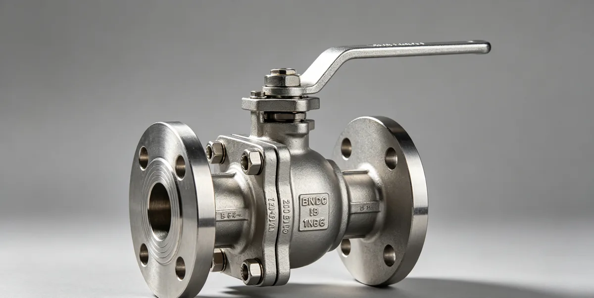
Component Breakdown
A ball valve consists of the following principal structural components, each with a defined engineering function:
- Valve body: The primary pressure-retaining casting or forging that contains all internal components and provides the inlet and outlet end connections. The body material is selected based on the required ASME B16.34 pressure class at design temperature, fluid chemical compatibility, and sour service NACE MR0175 hardness requirements. Common body materials include ASTM A216 WCB (carbon steel, Class 150–1500), ASTM A351 CF8M (316 stainless, Class 150–1500), ASTM A352 LCC (cryogenic service to −46°C), and ASTM A995 4A / 6A (Duplex stainless for corrosive service). Ball valve bodies are manufactured in three primary configurations: one-piece (welded or top-entry), two-piece (split axially at the ball centerline for seat ring removal), and three-piece (removable center section for in-line seat and ball maintenance without removing the valve from the pipeline).
- Ball: The spherical closure element with a precision-machined through-bore. The ball must maintain its spherical geometry within tight tolerances — typically ±0.01 mm on the seating radius for soft-seated valves — to ensure consistent sealing contact with the seats across the full operating temperature and pressure range. Ball materials must be compatible with the process fluid and must provide adequate surface hardness to resist seat wear and erosion. Solid stainless steel balls (ASTM A276 Type 316) are standard for general service. Balls with Stellite or Inconel 625 weld overlay on the seating band are specified for high-temperature metal-seated service and for sour gas service where NACE MR0175 compliance must be maintained.
- Seat rings: The sealing elements that contact the ball surface in the closed position and provide the pressure boundary between the upstream and downstream sides of the valve. In floating ball valves, the downstream seat receives the full hydraulic thrust load (F = ΔP × bore area) and must structurally withstand this load while maintaining a gas-tight seal. In trunnion-mounted valves, the seats are spring-loaded and the hydraulic thrust is absorbed by the trunnion bearings rather than the seats. Soft seats (PTFE, PEEK, or elastomer inserts in a metallic carrier ring) achieve ANSI/FCI 70-2 Class VI zero-leakage performance; metal seats (Stellite or Inconel 625 hardfaced in a metallic seat ring) are required above 200°C (PTFE limit) or 250°C (PEEK limit) and in abrasive or fire-safe service.
- Stem: The torque transmission shaft connecting the actuator to the ball. The stem must have adequate torsional strength to transmit the maximum required breakaway torque without yielding, and must incorporate a blow-out proof geometry (a shoulder wider than the stem bore through the packing gland) per API 6D and ISO 17292 requirements. The stem penetrates the valve body through the bonnet bore and is sealed by the stem packing — flexible graphite rings for high-temperature or general service, or PTFE V-ring packing for corrosive or low-torque service.
- Packing gland and stem seals: The dynamic sealing system between the rotating stem and the bonnet bore that prevents leakage of process fluid along the stem to atmosphere. The packing gland is bolted to the bonnet and pre-loads the packing rings against the stem to provide the required sealing compression. Anti-static devices — a spiral spring or conductive wire between stem and body — provide electrical continuity between the ball, stem, and body (resistance ≤ 10 Ω per ISO 17292 and API 6D) to prevent electrostatic charge buildup from flowing fluid, which could cause ignition in hydrocarbon service.
- Body cavity drain and vent: Trunnion-mounted ball valves in Double Block and Bleed (DBB) configuration incorporate a body cavity drain or vent connection that allows the trapped cavity between the two seats to be depressurized and vented to confirm that both seats are sealing. The body cavity connection is a critical functional element of the DBB isolation capability required by API 6D for safe maintenance isolation.
Structure Diagram Explanation
The internal assembly of a two-piece floating ball valve, assembled from inlet side to outlet side along the flow axis, is as follows: the inlet body half contains the upstream seat ring pocket, precision-machined to locate the upstream seat ring at the correct distance from the ball centerline. The ball is then placed into the upstream seat ring, engaging the flat-drive slot on the ball top with the stem lug. The downstream body half is brought over the ball, capturing the downstream seat ring in its pocket against the ball surface. The two body halves are joined by threaded engagement or bolted flange with ASME B16.20 ring gasket or raised face spiral wound gasket, torqued to the required assembly load to pre-compress the seat rings against the ball to the design pre-load.
In a three-piece ball valve — the preferred design for services requiring in-line maintenance — the center body section captures both seat rings and the ball, while the two end body sections provide the pipeline end connections. The center section can be removed from the pipeline by disconnecting the two bolted flanges joining it to the end sections, allowing the ball and seats to be inspected, cleaned, lapped, or replaced without removing the end connections from the pipeline. This in-line maintenance capability significantly reduces the maintenance time and associated production shutdown duration for large-bore, high-pressure ball valves where removing the complete valve from the line would require cutting the pipeline weld.
3. Advantages and Disadvantages
Engineering Advantages
The ball valve offers a combination of engineering performance characteristics that make it the dominant isolation valve type across the majority of industrial process and pipeline applications:
- Lowest fully-open pressure drop of any isolation valve type: Full-bore ball valves have a resistance coefficient K of approximately 0.05–0.15, compared to 3–10 for globe valves and 0.1–0.3 for gate valves at equivalent bore and velocity. Over a 20-year service life at continuous operation, this pressure drop advantage translates to measurable energy savings in pump or compressor power consumption.
- Fast quarter-turn actuation: The 90° travel from fully closed to fully open is completed in 1–3 seconds for a typical pneumatically actuated ball valve, enabling rapid process response and fast emergency shutdown. This speed advantage — compared to 15–60 seconds for equivalent multi-turn gate or globe valves — is critical for Emergency Shutdown (ESD) valve applications where response time is a safety-critical parameter.
- Excellent zero-leakage shutoff: Soft-seated ball valves achieve ANSI/FCI 70-2 Class VI (zero-detectable leakage) in gas and liquid service — the highest available leakage class. This zero-leakage performance is achieved through the pressure-energized sealing mechanism of the floating configuration: upstream pressure pushes the ball against the downstream seat, creating a contact force that increases with differential pressure and self-reinforces the seal under operating conditions.
- Bidirectional shutoff capability (trunnion DBB designs): Trunnion-mounted ball valves with spring-loaded bidirectional seats provide Double Block and Bleed (DBB) functionality per API 6D — simultaneously isolating upstream and downstream pressure sources while providing a body cavity vent to confirm isolation integrity. This capability makes trunnion ball valves the standard choice for safe maintenance isolation in oil and gas production systems.
- Wide pressure class and bore size range: Ball valves are commercially available from NPS ½ through NPS 60 and beyond, in pressure classes from Class 150 through Class 4500 — the widest application range of any valve type. This range covers virtually every industrial process and pipeline application from small instrument isolation to large-diameter high-pressure trunk pipeline isolation.
- Pipeline pigging compatibility (full-bore designs): Full-bore ball valves allow pipeline inspection gauges (pigs), cleaning pigs, and intelligent inspection tools to pass through the valve without restriction — an essential requirement for pipeline systems that require periodic internal inspection and cleaning.
- Compact face-to-face dimensions: Ball valve face-to-face dimensions per ASME B16.10 are significantly shorter than equivalent gate or globe valves at the same pressure class and bore, providing installation space savings in pipe racks and modules where structural space is at a premium.
Engineering Limitations and Drawbacks
Despite their dominant position in isolation valve service, ball valves have characteristic limitations that must be recognized and addressed in application engineering:
- Poor throttling characteristic in standard designs: The cylindrical bore ball produces a quick-opening Cv-versus-angle characteristic — most of the Cv change occurs in the first 30–40° of opening, leaving approximately 50–90° of the travel range with relatively small Cv changes. This makes standard round-bore ball valves highly sensitive and difficult to control near the closed position, producing flow instability and seat erosion. Characterized V-port or segmented ball designs address this limitation at the cost of increased manufacturing complexity and higher procurement cost.
- Seat erosion in throttling service: When operated in partially open position for throttling, the high-velocity flow through the restricted bore gap between the ball surface and the seat ring produces seat wire-drawing erosion — a progressive cutting of the soft seat insert by the high-velocity, high-energy flow. This erosion reduces seat contact area, increases leakage, and eventually renders the valve unable to meet its leakage class requirement. Ball valves must either be applied strictly for on-off service, or must be specified with characterized trim and erosion-resistant metal seats for throttling service.
- High cost for large-bore, high-pressure configurations: Trunnion-mounted ball valves in large bore sizes (above 16 inches) at high pressure classes (Class 900 and above) represent some of the most expensive, heaviest, and longest-lead-time items in the valve specification. A 24-inch Class 1500 trunnion ball valve may weigh 8,000–15,000 kg and carry a procurement cost of USD 150,000–400,000 with a lead time of 40–60 weeks. At this scale, butterfly valves or gate valves may provide adequate performance at significantly lower cost, weight, and delivery time — the economic case for ball valve selection must be justified by the specific performance requirements (full bore, DBB, fast actuation) that only the ball valve can provide.
- Cavity trapping in solids-laden service: The body cavity between the ball and the body bore in floating ball valve designs can trap solid particles, hydrate crystals, or viscous fluid deposits during operation. On valve closure, these trapped solids can prevent the ball from seating fully or can score the ball and seat surfaces. Cavity-filled ball valves (with solid packing that eliminates the cavity), or injection-fitted designs (with grease injection ports for cavity purging), must be specified for services with significant solids content.
- Thermal expansion in very high-temperature cycling service: In severe thermal cycling service — where the valve is repeatedly heated to high temperature and cooled to near-ambient — the differential thermal expansion between the ball and the body can cause the ball to bind against the seats or produce over-compression of soft seat inserts, leading to accelerated creep and premature seat failure. Extended service intervals above 250°C with repeated thermal cycling require specialist trunnion valve designs with engineered thermal expansion accommodation in the bearing and seat spring system.
4. Industrial Applications and Use Cases
Common Industrial Sectors
Ball valves serve as the primary isolation valve type across a wide range of industrial sectors, each with distinct performance requirements:
- Oil and Gas Production and Pipeline: Ball valves are the dominant valve type in upstream production, gathering, transmission, and distribution pipeline systems. Trunnion-mounted ball valves in API 6D design, with fire-safe qualification per API 607, NACE MR0175 sour service compliance, and DBB sealing capability, provide the block isolation, ESD, and safe maintenance isolation functions required by the process safety concept. Wellhead master valves, wing valves, and pipeline block valves are almost universally ball valves in sizes from NPS 2 through NPS 36 and pressure classes from Class 600 through Class 2500. Pigging stations require full-bore ball valves to allow inspection and cleaning tools to pass without obstruction.
- Petrochemical and Refinery Processing: Ball valves serve block isolation, ESD, and line break functions in petrochemical process units — ethylene crackers, polyethylene/polypropylene units, LNG liquefaction and regasification, hydrogen production, and refinery processing units. High-alloy ball valves in Duplex 2205, Super Duplex 2507, or Inconel 625 body materials serve corrosive service in HF alkylation, sulfuric acid service, and high-chloride process streams. Cryogenic-extension ball valves with extended body and bonnet serve LNG production and storage service at −162°C. For reference to related shutoff isolation options, see Gate Valve.
- Power Generation: Ball valves in carbon steel and alloy steel body construction serve fuel gas isolation, instrument air isolation, and cooling water isolation in thermal power plants. For main steam and feedwater service above 300°C, gate valves with pressure-seal bonnets are generally preferred over ball valves due to their superior thermal cycling performance at very high temperature, but ball valves serve the majority of auxiliary and instrument isolation functions throughout the power plant balance of plant.
- Water and Wastewater Treatment: Ball valves in stainless steel or PVC/CPVC body construction serve isolation and flow control in chemical dosing systems, UV disinfection units, membrane filtration skids, and chlorination systems. Their compact dimensions and zero-leakage soft seats make them preferred over gate valves for the frequent cycling and chemical resistance requirements of water treatment chemical handling. For large-bore main water line isolation above 12 inches, butterfly valves typically replace ball valves on weight and cost grounds.
- Chemical Processing and Pharmaceutical: Ball valves in high-purity 316L stainless steel (electropolished for pharmaceutical), Hastelloy C-276, or PTFE-lined body construction serve isolation and sampling in pharmaceutical manufacturing, fine chemical synthesis, and specialty chemical handling. PTFE-lined ball valves provide corrosion resistance to strong acids and caustic solutions in chemical process service where bare stainless steel body would be rapidly attacked.
Typical Engineering Scenarios
The following service condition combinations illustrate how ball valve design parameters are determined from operating requirements:
- High-pressure sour gas isolation (150 bar, 250°C, H₂S service, 12-inch): Trunnion-mounted ball valve, ASTM A216 WCB carbon steel body with NACE MR0175 hardness certification (body hardness ≤22 HRC), Inconel 625 overlay on ball seating band and seat ring faces, spring-loaded seats, fire-safe design per API 607, DBB per API 6D, anti-static device, blow-out proof stem, hydraulic spring-return actuator sized for 2.0× calculated breakaway torque. Pressure class confirmed from ASME B16.34 Group 1.1 P-T table at 250°C → Class 1500 minimum. For the systematic pressure class determination process, refer to Pressure Class Selection.
- Cryogenic LNG isolation (−162°C, 80 bar, LNG service, 8-inch): Floating or trunnion-mounted ball valve (trunnion preferred for 8-inch at 80 bar), ASTM A351 CF8M (316 stainless) body, cryogenic extension bonnet (minimum 150 mm extension to keep packing above −29°C), PTFE seats (qualified for cryogenic service per BS 6364), low-temperature fire-safe design, all body cavity vent and drain connections with secondary isolation for LNG containment. For detailed material selection guidance at low temperature, refer to Temperature Rating.
- Clean natural gas metering station isolation (70 bar, 50°C, natural gas, 6-inch): Floating ball valve, ASTM A216 WCB carbon steel body, PTFE seats for Class VI zero-leakage shutoff, fire-safe design, anti-static, blow-out proof stem, pneumatic spring-return actuator for fail-closed ESD function. Floating configuration is structurally valid at 6-inch Class 600 with the 70 bar operating differential pressure, as the seat load F = 70 bar × π × (0.15 m)² = approximately 50,000 N (5 tonnes) — within the structural capacity of PTFE seat inserts with an appropriate metallic carrier ring. Nominal bore confirmed as 6-inch from independent Cv sizing calculation: Valve Size Calculation.
- Corrosive acid chemical service (10 bar, 80°C, 10% HCl, 3-inch): PTFE-lined ball valve (PTFE body lining, PTFE-coated ball, PTFE seats, and PTFE stem seal) in carbon steel or ductile iron outer body. The PTFE lining provides complete isolation of all metallic body surfaces from the highly corrosive HCl fluid — the metallic body serves only as structural containment for the pressure-rated PTFE liner. Operating pressure and temperature are well within the PTFE liner’s rated limits (maximum pressure typically 16–25 bar for PTFE-lined ball valves in standard body designs; maximum temperature approximately 150°C for sustained PTFE service).
5. Relevant Standards and Codes
Applicable International Standards
Ball valves for industrial service are governed by the following primary international standards, each addressing a distinct scope of design, material, and testing requirements:
- API 6D — Specification for Pipeline and Piping Valves: The primary standard for ball valves in oil and gas pipeline and gathering systems. API 6D governs: body wall minimum thickness (calculated from bore size and pressure class); bore geometry — full bore defined as bore diameter ≥ 95% of nominal pipe inside diameter; reduced bore defined as bore diameter ≥ 70% of nominal pipe inside diameter; fire-safe design qualification by reference to API 607 (soft-seated valves) or API 6FA (metal-seated valves); anti-static device requirements (resistance ≤ 100 Ω between stem and body per API 6D, more stringent than ISO 17292’s 10 Ω); blow-out proof stem requirements; Double Block and Bleed sealing capability; low-pressure gas seat test at 5.5–6.9 bar air or nitrogen (zero leakage for soft seats); high-pressure liquid seat test at rated pressure (zero leakage for soft seats, 0.1 mL/min/NPS maximum for metal seats); and shell hydrostatic test at 1.5× rated pressure. API 6D also requires the drive train — stem, key, coupling, and actuator mounting — to be designed for at least 2.0× the calculated maximum breakaway torque at design differential pressure, ensuring that the actuator can reliably operate the valve under worst-case conditions.
- ASME B16.34 — Valves: Flanged, Threaded, and Welding End: Provides the pressure-temperature rating framework for all ball valve body designs in all pressure classes from Class 150 through Class 4500. The P-T tables in ASME B16.34 — organized by material group and temperature — define the rated working pressure (MAWP) at each operating temperature. The MAWP at design temperature, not the class nominal pressure at ambient temperature, is the governing structural limit. Temperature derating is significant: a Class 900 WCB carbon steel ball valve has a nominal pressure rating of approximately 153 bar at ambient temperature, but this rating reduces to approximately 137 bar at 250°C and approximately 117 bar at 350°C per ASME B16.34 Group 1.1 tables.
- API 598 — Valve Inspection and Testing: Specifies factory acceptance test requirements and leakage acceptance criteria for ball valves: shell hydrostatic test at 1.5× rated pressure; low-pressure gas closure test at approximately 6 bar; high-pressure liquid closure test at rated pressure. For soft-seated ball valves, API 598 requires zero leakage at both closure tests. For metal-seated ball valves, API 598 permits a maximum of 20 bubbles per minute (at the low-pressure gas test) and 20 drops per minute (at the high-pressure liquid test) for valves DN ≤ 100 mm (NPS 4), with higher allowances for larger sizes. These acceptance criteria are the quantitative pass/fail thresholds for every ball valve leaving the manufacturer’s facility.
- ISO 17292 — Metal Ball Valves for Petroleum, Petrochemical, and Allied Industries: Governs the design and qualification requirements for metal ball valves in DN 15 to DN 600 (NPS ½ to NPS 24) for flanged and butt-welded end connections. ISO 17292 mandates: anti-static design with resistance ≤ 10 Ω between ball, stem, and body; blow-out proof stem with stem-to-ball torsional connection strength exceeding external stem strength by at least 10%; fire-safe design qualification per ISO 10497; and seat ring material specification documented in the manufacturer data sheet with chemical compatibility qualification for the service fluid.
How These Standards Affect Design and Selection
The combined effect of the applicable standards on ball valve design and specification is to define every measurable performance parameter — structural, functional, and safety — that a ball valve must meet before it can be specified for a given service:
- Pressure class confirmation: ASME B16.34 forces the engineer to confirm the valve’s rated pressure at the actual design temperature — not at ambient temperature. This prevents the common error of specifying a Class 600 valve for a 100-bar design pressure at 300°C, where the Class 600 rating at 300°C (approximately 88 bar for WCB carbon steel per ASME B16.34 Group 1.1) falls below the design pressure, requiring upgrade to Class 900.
- Factory test traceability: API 598 and API 6D factory acceptance test records — shell test, low-pressure seat test, and high-pressure seat test — must accompany every ball valve as part of the quality documentation package. Valves without complete, traceable test documentation must not be accepted at goods receipt, regardless of other quality certificates present.
- Drive train sizing: The API 6D 2.0× drive train safety factor requirement forces the engineer to size actuators, stems, and keys for twice the calculated worst-case breakaway torque. This margin ensures that thermal expansion, seat degradation, and actuator air supply pressure variation within the acceptable range cannot prevent the valve from operating when required — a direct safety reliability requirement for ESD and isolation valve applications.
- Fire-safe secondary seal: The API 607 and ISO 10497 fire-safe qualification requirement mandates that all ball valves in hydrocarbon service incorporate a secondary metal-to-metal seal that limits leakage to within the defined fire-condition acceptance rates (typically 0.4 mL/minute per NPS of nominal bore in liquid test at rated pressure) after the primary soft seat has been destroyed by fire exposure. This requirement means that a soft-seated ball valve cannot be accepted for hydrocarbon service without confirmed fire-safe qualification — the valve datasheet must reference the fire test certificate number and testing standard explicitly.
6. Related Valve Types and Internal Linking
Ball valves are the most widely applied industrial valve type, but each specific application should be evaluated against alternative valve types before final specification. The following related valve type pages provide comparable engineering depth for each design — use them in conjunction with the valve selection module to confirm that a ball valve is the optimum type for your specific service conditions:
- Industrial Valve Types Overview — The complete engineering summary of all valve types, working principles, structural anatomy, comparative advantages, and applicable standards across the full valve types cluster
- Gate Valve — Full-bore, on-off isolation valve for low-frequency-operation service; the primary alternative to ball valves in large-bore, Class 900+ steam and refinery service where thermal cycling performance and full-bore pig passage are required
- Globe Valve — Multi-turn throttling and flow control valve with inherently stable Cv-versus-stroke characteristic; the preferred alternative to ball valves in applications requiring continuous flow modulation and high positional resolution
- Check Valve — Self-actuating non-return valve; installed in combination with ball valve isolation in pump and compressor discharge lines to prevent reverse flow during shutdown
- Butterfly Valve — Compact, lightweight quarter-turn disc valve; the primary alternative to ball valves in large-bore, low-pressure services (above 12 inches, Class 150–300) where ball valve weight and cost are prohibitive
- Plug Valve — Quarter-turn cylindrical or tapered plug valve; an alternative to ball valves in multi-port flow diversion service and in PTFE-sleeved designs for corrosive chemical service
- Needle Valve — Precision low-flow throttling valve for instrument connections, sample lines, and chemical injection — typically installed in series with a ball valve isolation upstream for safe maintenance access