
Compare: Ball valve vs butterfly valve — differences, when to use each & cost
For a complete guide to industrial valve types, visit the
Industrial Valve Types Overview page.
1. Working Principle
Basic Operating Mechanism
A butterfly valve controls fluid flow by rotating a circular disc — the butterfly — about a diametrical shaft axis that passes through the center of the disc and the valve body. When the disc plane is parallel to the pipe flow axis (disc edge-on to the flow), the valve is fully open; when the disc plane is perpendicular to the pipe flow axis (disc face-on to the flow), the valve is fully closed and the disc perimeter compresses against the seat ring to form the pressure seal. This 90° quarter-turn rotation — identical in actuation mechanism to a ball valve — is the defining operational characteristic of the butterfly valve, providing fast actuation speed and simple actuator design.
The shaft connects the disc to the external actuating mechanism — manual lever or gear operator, pneumatic quarter-turn actuator, or electric quarter-turn actuator. Rotation of the shaft transmits directly and rigidly to the disc through a fixed connection, with no lost motion between shaft rotation and disc angular position. Unlike the ball valve, where the closure element (ball) is entirely within the body cavity and does not intrude into the pipe bore in the open position, the butterfly valve disc is permanently within the pipe bore across the full travel range — edge-on in the fully open position, and face-on in the fully closed position. This permanent disc intrusion is the fundamental geometric constraint that defines the butterfly valve’s application envelope. For system-level valve selection strategy, see How to Select an Industrial Valve. For the Cv-based sizing methodology that determines the required butterfly valve bore size for your flow duty, visit Cv Value Explained.
Operating Physics and Flow Behavior
The flow behavior through a butterfly valve across its full 0°–90° travel range is governed by the projected area of the disc relative to the pipe bore cross-sectional area, and by the complex three-dimensional flow field generated by the disc’s interaction with the fluid stream:
- Fully open pressure drop: In the fully open position (disc parallel to flow axis), the disc remains edge-on in the flow stream, occupying a thin crescent-shaped obstruction within the pipe bore. The disc thickness and the shaft diameter together reduce the effective flow area by approximately 5–15% of the full pipe bore area depending on disc and shaft geometry. This produces a resistance coefficient K of approximately 0.3–1.5 for concentric butterfly valves at full open — higher than full-bore ball valves (K = 0.05–0.15) and gate valves (K = 0.1–0.3), but substantially lower than globe valves (K = 3–10). For large-bore services (above 24 inches) where the absolute weight and cost advantage of the butterfly valve over ball and gate valves is greatest, this modest increase in fully-open pressure drop is generally acceptable within the system hydraulic budget.
- Throttling characteristic: The butterfly valve’s Cv-versus-angle characteristic is approximately sinusoidal — Cv increases slowly from 0° (closed) to approximately 30° opening, then increases more steeply through 30°–70°, then flattens as the disc approaches 90° (fully open). This modified quick-opening characteristic provides better throttling resolution than a standard round-bore ball valve near the closed position, but less precise control than a characterized globe valve across the full travel range. For modulating control applications with butterfly valves, the usable control range is typically 20°–70° of disc rotation — operating below 20° opening produces high-velocity disc erosion from the restricted flow, and operating above 70° provides insufficient Cv sensitivity for meaningful flow adjustment. For high-precision control applications requiring operation across the full Cv range, characterized globe valves or V-port ball valves provide superior control characteristic compared to butterfly valves.
- Disc geometry effect on flow field: In the partially open position, the butterfly valve disc splits the flow stream into two asymmetric channels on either side of the disc — one side with larger flow area (the downstream-facing side) and one with smaller area (the upstream-facing side). This asymmetric flow field generates a hydrodynamic torque on the disc that acts in the closing direction for disc angles between approximately 20° and 70° — the disc “wants” to close under the fluid pressure when partially open. The actuator must be sized to overcome this closing torque throughout the control range, and the actuator-disc shaft connection must be rigid enough to prevent disc flutter under the varying hydrodynamic torque at different throttling positions.
- Seat contact mechanism by valve design type: The three primary butterfly valve design types — concentric, double-offset, and triple-offset — produce fundamentally different disc-to-seat contact mechanisms that determine their applicable pressure class, temperature range, and leakage class:
- Concentric (centric): The shaft axis passes through the center of the disc and the seat ring bore — disc and seat are concentric with the pipe bore. Closing the valve compresses the disc perimeter into the resilient elastomer seat ring by a uniform radial interference fit. The disc rubs against the seat throughout the full 90° travel — generating continuous sliding friction that produces seat wear in high-cycle applications. Maximum pressure class typically Class 150–300; seat materials (EPDM, NBR, PTFE) limit maximum temperature to approximately 120–180°C.
- Double-offset (high-performance): The shaft axis is offset from the disc centerline in two directions — offset behind the disc center (preventing seat rubbing through most of the disc travel) and offset from the pipe bore centerline (creating a cam action that drives the disc into the seat only in the final degrees of closure). This double offset eliminates seat rubbing through most of the travel, extending seat life and reducing operating torque. PTFE or metal seat inserts; applicable to Class 150–600 in most designs.
- Triple-offset (metal seated): A third offset — the seat cone axis is inclined at an angle relative to the pipe bore axis — creates a pure cam seating action with zero sliding contact between disc and seat throughout the entire travel. The disc contacts the seat only at the fully closed position, with no rubbing or friction during opening or closing. Metal-to-metal conical seat contact provides fire-safe capability, bubble-tight shutoff, and applicability to Class 150–600 (and Class 900 in specialized designs) with temperatures up to approximately 600°C for high-alloy versions.
2. Structural Diagram and Anatomy
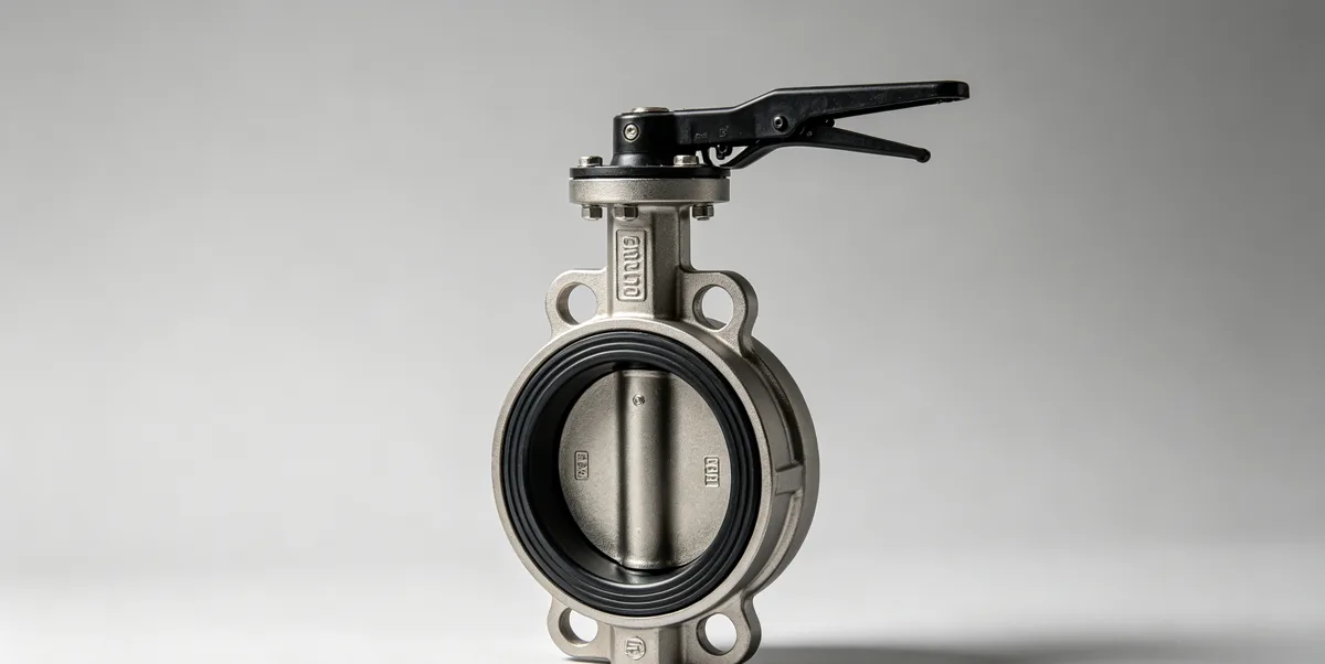
Component Breakdown
A butterfly valve consists of the following principal structural components:
- Valve body: The short cylindrical ring that provides the flow bore, seat ring retention geometry, shaft bearing bores, and the body-to-pipeline connection. Butterfly valve body face-to-face dimensions are dramatically shorter than equivalent ball, gate, or globe valve designs — a 12-inch Class 150 wafer butterfly valve body is typically 43–57 mm face-to-face (per EN 558 Series 20), compared to approximately 330 mm for an equivalent flanged ball valve per ASME B16.10. This compact face-to-face dimension is the butterfly valve’s most significant dimensional advantage. Body end connection types:
- Wafer body: No integral flanges — the body is clamped between two pipeline flanges using through-bolts that pass through the pipeline flange bolt holes and span the valve body. Least expensive and lightest configuration; requires both pipeline flanges to be present simultaneously for installation and removal — cannot be used at the end of a pipeline or where single-side removal is required.
- Lug body: Threaded bolt lugs cast into the body perimeter allow the butterfly valve to be bolted to each pipeline flange independently. The valve can be removed from one side of the pipeline without disturbing the other — providing a “dead-end service” capability where the downstream pipeline can be disconnected with the valve closed and line pressure on the upstream side. Required for all end-of-line service and where the downstream piping may be removed for maintenance with the valve as the end isolation.
- Flanged body: Integral raised-face flanges on both body ends, bolted directly to pipeline flanges with gaskets. Provides the most robust body-to-pipeline connection; required for Class 600 and above double-offset and triple-offset designs where the higher disc-to-seat contact force requires a more rigid body-to-flange connection than wafer or lug designs provide.
Body materials: ductile iron (ASTM A536, for water and utility service), carbon steel (ASTM A216 WCB, for process service), stainless steel (CF8M, for corrosive service), and high-alloy castings for specialty services.
- Disc: The circular closure element that rotates about the shaft axis. Disc geometry in triple-offset designs is conical-faced rather than flat — the disc seating face is machined as a truncated cone that matches the conical seat ring geometry, providing line contact sealing that distributes closure force along the full disc perimeter. Disc materials must be compatible with the process fluid chemistry and temperature, and must provide adequate corrosion resistance and surface hardness for seat contact wear life. Carbon steel discs with Stellite weld overlay on the seating cone face are standard for triple-offset metal-seated designs in hydrocarbon service; stainless steel or duplex stainless discs are used for corrosive service.
- Shaft (stem): The diametrical shaft passing through the disc center and extending through the body shaft bores to the actuator mounting. The shaft transmits actuator torque to the disc and must be sized to withstand the maximum combined torque from: hydrodynamic closing torque at the maximum design differential pressure at the most adverse throttling angle, actuator breakaway torque, and packing friction torque. Blow-out proof shaft design — a shaft shoulder wider than the body shaft bore — prevents the shaft from being ejected under internal pressure in the event of external shaft seal failure, consistent with the same blow-out proof stem requirements applied to ball and globe valves per API and ISO standards.
- Seat ring: The sealing element in the body bore that the disc perimeter compresses against in the closed position. In concentric designs, the seat is a resilient elastomer ring (EPDM, NBR, or neoprene) molded into or pressed into the body bore, providing interference-fit sealing throughout the full 90° travel. In double-offset designs, the seat is a PTFE or metal insert ring precision-machined to match the disc perimeter geometry. In triple-offset designs, the seat is a precision-machined metal cone ring (Stellite, Inconel 625, or 316 stainless) that matches the disc’s conical seating face — providing the metal-to-metal contact that achieves fire-safe qualification and tight shutoff at elevated temperature and pressure.
- Shaft bearings and packing: Sleeve bearings in the body shaft bores support the shaft radially under the disc’s hydrodynamic load, while the packing glands at the external shaft exits provide the dynamic seal preventing process fluid leakage along the shaft. PTFE-impregnated woven packing provides low-friction shaft sealing for standard service; flexible graphite packing is required for high-temperature applications above the PTFE thermal limit.
Structure Diagram Explanation
In a wafer-body concentric butterfly valve, the assembly sequence from the pipeline perspective is: the two pipeline flanges are present with gaskets, the wafer body is centered between them with the shaft horizontal, through-bolts are inserted through the outer pipeline flange bolt holes spanning across the body, and nuts are torqued to the flange bolt specification. The disc shaft extends through the body to the actuator mounting face on the top of the body. The actuator mounts on a standard ISO 5211 actuator mounting pad with a double-D or keyway shaft connection that engages the shaft’s flat drive.
For maintenance access, the elastomer seat ring in a concentric wafer design is replaceable in-situ after removing the valve from the pipeline (wafer body removal requires access to both flanges simultaneously). The disc is removable after seat ring removal for inspection of disc face coating and shaft bearing condition. In triple-offset flanged designs, the metal seat ring is a bolted or threaded insert accessible after removing the body flange bolting, allowing seat ring replacement without body removal from the line in some configurations. Shaft packing replacement is performed in-situ with the valve isolated — the gland follower is unbolted, worn packing rings are removed and replaced with new rings, and the gland is re-torqued to the manufacturer’s specified compression load.
3. Advantages and Disadvantages
Engineering Advantages
Butterfly valves provide a specific combination of engineering performance characteristics that make them the dominant valve type for large-bore, moderate-pressure applications:
- Lowest weight and smallest installation envelope of any valve type at large bore: A 24-inch Class 150 wafer butterfly valve weighs approximately 80–150 kg, compared to approximately 1,500–3,000 kg for a 24-inch Class 150 full-bore ball valve and approximately 800–1,500 kg for an equivalent gate valve. This 10–20× weight reduction dramatically reduces the structural support requirement and lifting equipment needed for installation — a major advantage in offshore platforms, elevated pipe racks, and any installation where structural load capacity is constrained. The compact face-to-face dimension (43–70 mm for a 24-inch wafer butterfly valve versus approximately 600 mm for an equivalent ball valve) provides proportional savings in piping material and installation space.
- Lowest procurement cost at large bore: At bore sizes above 12 inches, butterfly valves are typically 20–50% of the procurement cost of equivalent full-bore ball valves and 40–70% of equivalent gate valve cost. For large water treatment, HVAC, and utility systems with hundreds of large-bore isolation valves, this cost differential represents a significant project capital cost saving.
- Fast quarter-turn actuation: The 90° quarter-turn travel from fully closed to fully open is completed in 1–5 seconds for a typical pneumatically actuated butterfly valve, providing fast response for process control and automated on-off service. The actuator torque requirement is lower than for an equivalent ball valve at the same bore and pressure class in most service conditions — reducing actuator size, weight, and cost.
- Suitable for throttling at moderate precision: Double-offset and triple-offset butterfly valves provide acceptable throttling characteristics for flow regulation applications that do not require the high precision of a globe valve control loop. In large-bore water treatment and HVAC applications, butterfly valve throttling provides the level of flow regulation accuracy adequate for the process requirements at substantially lower cost and weight than globe valve alternatives.
- Triple-offset designs extend to high-performance service: Triple-offset metal-seated butterfly valves achieve bubble-tight shutoff, fire-safe qualification per API 607, and applicability to Class 600 (and in some designs Class 900) — extending the butterfly valve’s service envelope to moderate hydrocarbon process service where its weight and cost advantages over ball valves can be realized without sacrificing fire-safe or tight-shutoff performance.
Engineering Limitations and Drawbacks
Butterfly valves have well-defined limitations that must be recognized and respected in application engineering:
- Permanent disc intrusion — no pipeline pigging capability: The butterfly valve disc is permanently within the pipe bore at all positions, including the fully open position. The disc edge projects into the flow stream even at 90° open, producing an obstruction that prevents pipeline inspection tools (PIGs), cleaning pigs, and intelligent inspection tools from passing through. Butterfly valves cannot be specified for any pipeline segment that requires internal pigging — full-bore ball valves or gate valves with gate fully retracted are required for pig-compatible service.
- Concentric designs limited to Class 150–300 and moderate temperature: Standard concentric resilient-seat butterfly valves are structurally rated only to Class 150–300 in most designs, and the elastomer seat materials (EPDM, NBR) limit maximum service temperature to approximately 120–180°C. In higher-pressure or higher-temperature hydrocarbon service, standard concentric butterfly valves cannot be specified — double-offset or triple-offset designs are required, at significantly higher cost that reduces the butterfly valve’s economic advantage over ball valve alternatives.
- Hydrodynamic disc torque requires careful actuator sizing: The asymmetric flow field around the partially open disc generates a significant hydrodynamic closing torque that varies with disc angle and differential pressure. This torque must be calculated at each disc position across the full operating range, and the actuator must be sized to overcome the maximum hydrodynamic torque with an adequate safety factor at minimum instrument air pressure or electrical supply. Undersized actuators on butterfly valves in high-flow, high-differential-pressure throttling service will stall at specific disc angles — a failure mode that appears as intermittent control loop problems and is difficult to diagnose without actuator torque data.
- Disc erosion in high-velocity partially-open service: When operated below approximately 20° opening in high-velocity service, the narrow gap between the disc perimeter and the body bore generates an extremely high-velocity jet that impinges directly on the disc face and body bore surface. At liquid velocities above approximately 3–5 m/s in this restricted condition, erosion of the disc face coating and body bore surface occurs rapidly. Butterfly valves must not be specified for continuous throttling service at very small opening angles in high-velocity, solids-containing, or erosive fluid service.
- Wafer body cannot serve end-of-line or single-flange removal: Wafer butterfly valve bodies require both upstream and downstream pipeline flanges to be present simultaneously. They cannot be used at the end of a pipeline, at a vessel or pump nozzle where one side has no flange, or where the downstream piping will be removed with the valve in the closed position under line pressure. Lug-body designs are required for these installation configurations, at higher cost and weight.
4. Industrial Applications and Use Cases
Common Industrial Sectors
Butterfly valves serve specific and well-defined applications where their large-bore, lightweight, low-cost construction provides decisive advantages over alternative valve types:
- Water Treatment and Distribution: Butterfly valves in ductile iron or carbon steel body with EPDM resilient seats are the dominant isolation and flow control valve in municipal water treatment plants, water transmission mains, pump stations, and water distribution networks in bore sizes from 4 to 72 inches. Their weight, cost, and face-to-face dimension advantages over gate valves at these large bore sizes — combined with adequate pressure class (Class 150, typically below 25 bar) and temperature performance for water service — make them the standard specification for water infrastructure worldwide. Electric-actuated butterfly valves serve the automated flow control functions in filter backwash, chemical dosing dilution, and distribution pressure zone management.
- HVAC and Building Services: Butterfly valves in ductile iron or stainless steel body with EPDM or PTFE-lined seats serve chilled water, heating hot water, condenser water, and cooling tower circuits in commercial and industrial buildings. The compact face-to-face dimension is particularly valued in building mechanical rooms where space is constrained. Low-leakage double-offset designs with PTFE seats serve the tighter shutoff requirements of air handling unit coil isolation and heat exchanger isolation in variable-flow HVAC systems.
- Oil and Gas — Large Bore, Moderate Pressure Utility Service: Triple-offset metal-seated butterfly valves serve large-bore (above 16 inches) on-off isolation in Class 150–600 hydrocarbon process service at onshore and offshore facilities — particularly in fire water main isolation, cooling water isolation, and produced water handling where the butterfly valve’s weight advantage over large-bore ball valves is critical for topside weight budget management. For comparison with ball valve designs in the same large-bore service, see Ball Valve. For gate valve alternatives in full-bore pigging-required services, see Gate Valve.
- Power Generation — Cooling Water and Low-Pressure Steam: Butterfly valves serve cooling water intake and discharge isolation, condenser water box isolation, and auxiliary steam isolation in thermal power plants. The very large bore sizes of cooling water systems (above 36 inches at intake screens and condenser water boxes) make butterfly valves the only practical valve type on weight and cost grounds — no competing valve type provides adequate functionality at acceptable weight and cost at 48–72 inch bore.
- Chemical Processing — Slurry and Corrosive Fluid Handling: PTFE-lined butterfly valves (PTFE body lining, PTFE disc coating, PTFE seat) serve corrosive acid and alkali process streams in chemical plants. The PTFE lining provides complete isolation of all metallic body surfaces from aggressive chemicals. Rubber-lined butterfly valves (natural rubber or neoprene body lining) serve abrasive slurry service in mineral processing — the resilient rubber lining provides abrasion resistance that metal-body designs cannot match in high-solids-content slurry service.
Typical Engineering Scenarios
The following scenarios illustrate how butterfly valve design parameters are determined from service conditions:
- Large-bore cooling water isolation (5 bar, 45°C, seawater, 36-inch): Concentric wafer butterfly valve, ductile iron body (ASTM A536 Grade 65-45-12) with fusion-bonded epoxy internal coating for seawater corrosion protection, EPDM resilient seat, disc in 316 stainless steel or Duplex 2205 for seawater corrosion resistance, Class 150. Gear operator for manual actuation or electric actuator for remote operation. Wafer body acceptable for this location — both upstream and downstream pipeline flanges are present. For bore size confirmation from the hydraulic flow calculation, refer to Valve Size Calculation.
- Large-bore produced water isolation (25 bar, 80°C, produced water with H₂S, 20-inch): Triple-offset metal-seated butterfly valve, carbon steel flanged body (ASTM A216 WCB, NACE MR0175 hardness qualified), Class 300, Stellite 6 weld overlay on disc seating cone and seat ring cone face (with NACE MR0175 Part 3 cobalt alloy qualification), fire-safe design per API 607, lug body for dead-end service capability at the vessel nozzle connection. This service demonstrates the triple-offset design’s capability to extend butterfly valve applicability into moderate-pressure sour hydrocarbon service while retaining the weight advantage over equivalent trunnion ball valves at 20-inch bore. For pressure class confirmation at 80°C service temperature, refer to Pressure Class Selection.
- PTFE-lined butterfly valve for concentrated acid service (10 bar, 60°C, 98% H₂SO₄, 8-inch): Concentric wafer butterfly valve, carbon steel outer body with full PTFE lining (body bore, disc coating, seat ring), Class 150. PTFE provides essentially universal chemical resistance to concentrated sulfuric acid at 60°C — the primary material selection driver in this application. The Class 150 pressure rating is adequate for the 10-bar service pressure. PTFE lining temperature limit (approximately 150°C sustained service) is comfortably above the 60°C operating temperature. For temperature and material limit guidance, refer to Temperature Rating.
5. Relevant Standards and Codes
Applicable International Standards
Butterfly valves for industrial service are governed by the following primary standards:
- EN 593 / ISO 10631 — Metallic Industrial Butterfly Valves: The primary European and international standard for metallic industrial butterfly valves, covering wafer, lug, and flanged body designs in DN 32 to DN 2000 (NPS 1¼ to approximately NPS 80) for PN 6 through PN 100 (approximately Class 75 through Class 600) pressure ratings. EN 593 specifies body wall minimum thickness, disc and shaft design requirements, seat ring material qualification and temperature limits, shaft seal design, face-to-face dimensions per EN 558, and factory acceptance test requirements. EN 593 addresses all three design types — concentric, double-offset, and triple-offset — with distinct structural and test requirements for each offset class.
- API 609 — Butterfly Valves: Double-Flanged, Lug- and Wafer-Type: The primary North American standard for butterfly valves in petroleum and natural gas industry service. API 609 covers Category A (concentric, resilient-seated, Class 150 and lower) and Category B (double-offset and triple-offset, Class 150 through Class 600) butterfly valve designs. API 609 specifies body wall thickness, disc and shaft structural requirements, seat material qualification, face-to-face dimensions per ASME B16.10, fire-safe design requirements (referencing API 607 for fire-safe testing), anti-static provisions, and factory acceptance tests. Category B API 609 valves are the standard specification for butterfly valves in North American oil and gas process service at Class 150 through Class 600.
- ASME B16.34 — Valves: Flanged, Threaded, and Welding End: Provides the pressure-temperature rating tables for flanged and butt-welding end butterfly valve body designs in all pressure classes from Class 150 through Class 4500. For butterfly valves with integral flanged bodies, ASME B16.34 body wall thickness requirements and P-T rating tables apply directly. Wafer and lug body designs without integral flanges are governed by EN 593 or API 609 for pressure class and wall thickness, but the P-T derating tables of ASME B16.34 or equivalent standard are referenced for confirming the rated pressure at design temperature for the body material selected.
- API 598 — Valve Inspection and Testing: Specifies factory acceptance test requirements for butterfly valves. API 598 defines three acceptance tests for butterfly valves: shell hydrostatic test at 1.5× rated pressure; low-pressure gas seat test; and high-pressure liquid or gas seat test. API 598 Table 3 permits higher maximum leakage rates for butterfly valves than for ball or gate valves, recognizing the inherent sealing geometry limitations of resilient-seat concentric designs: Class A maximum leakage (concentric resilient seat, Class 150–300) allows up to 100 mL/minute per inch of nominal bore in the gas seat test — significantly more permissive than the near-zero leakage of ball valves. Triple-offset metal-seated butterfly valves achieve tighter leakage performance and must meet the more stringent Class D leakage criteria in API 598 for metal-seated designs.
- API 607 — Fire Testing of Quarter-Turn Valves and Valves Equipped with Non-Metallic Seats: Fire-safe qualification standard for butterfly valves with non-metallic (elastomer or PTFE) seats. API 607 requires that a prototype valve of each design, size category, and seat material be exposed to fire conditions (approximately 750–870°C) for a minimum of 30 minutes, then pressurized and tested for external leakage (body and shaft seal) and seat leakage after cooldown. Triple-offset metal-seated butterfly valves are inherently fire-safe by design — the metal-to-metal seat sealing survives fire exposure without requiring a secondary seal. Concentric and double-offset resilient-seated designs require a secondary metal seal element that engages after the primary resilient seat has been destroyed by fire to meet API 607 leakage limits.
How These Standards Affect Design and Selection
The combined standards framework shapes butterfly valve specification and procurement decisions in the following specific ways:
- Design category selection — Category A versus Category B: API 609 Category A (concentric, resilient seat) and Category B (offset, metal or PTFE seat) valves have fundamentally different structural designs, pressure class limits, temperature limits, and leakage performance. The purchase specification must explicitly state which category is required — specifying only “butterfly valve per API 609” without the category designator is ambiguous and may result in delivery of a Category A valve when a Category B is required by the service conditions. Pressure class above Class 300, temperature above 180°C, hydrocarbon service requiring fire-safe qualification, or leakage class tighter than API 598 Table 3 Class A — any of these conditions mandates Category B specification.
- Face-to-face dimension standardization: ASME B16.10 and EN 558 standardize the face-to-face dimensions for butterfly valves by pressure class, bore size, and design series (wafer, lug, or flanged). Specifying compliance with the applicable face-to-face dimension standard ensures that a replacement butterfly valve from any compliant manufacturer can be installed in the same pipe spool without requiring piping modification — a critical procurement flexibility requirement for installed systems with long service lives and multiple future maintenance cycles.
- Leakage class clarification for gas service: API 598’s permissive butterfly valve leakage allowances (up to 100 mL/minute per inch of bore for Class A resilient-seated designs) may be adequate for water service but are completely unacceptable for hydrocarbon gas service where any seat leakage constitutes a safety hazard. Purchase specifications for butterfly valves in gas service must include a supplementary leakage requirement that overrides the API 598 standard allowance — typically requiring the valve to meet API 598 Class D (metal-seated) leakage criteria or ANSI/FCI 70-2 Class IV performance, which mandates a triple-offset metal-seated design regardless of the API 609 category designation.
6. Related Valve Types and Internal Linking
Butterfly valves occupy the large-bore, moderate-pressure segment of the industrial valve landscape — providing the most economical and lightweight solution for bore sizes above 12 inches in Class 150–600 service. For applications where butterfly valve limitations (disc intrusion, pressure class, fire-safe performance) require an alternative design, the following related valve type pages provide the engineering basis for evaluating the appropriate alternative. Use them with the valve selection module to confirm the optimum valve type for your specific service conditions across bore size, pressure class, temperature, fluid chemistry, and fire-safe requirements:
- Industrial Valve Types Overview — The complete engineering summary covering all valve types, working principles, structural anatomy, comparative advantages, and applicable standards across the full valve types cluster
- Ball Valve — The primary alternative to butterfly valves in moderate and large bore service requiring full-bore pigging capability, higher pressure class (Class 600 and above), DBB isolation, or fire-safe performance without a secondary seal; higher cost and weight than butterfly valves at equivalent large bore sizes
- Gate Valve — Full-bore isolation valve for large-bore pipeline service where pigging is required and butterfly valve disc intrusion is unacceptable; gate valve weight and face-to-face dimension disadvantages relative to butterfly valves are accepted where full-bore performance is mandatory
- Globe Valve — Precision throttling and flow control valve for applications requiring higher Cv control accuracy than butterfly valves can provide; higher pressure drop and smaller bore range than butterfly valves, but superior throttling characteristic for automated control loop service
- Check Valve — Self-actuating non-return valve installed alongside butterfly valve isolation in pump discharge and pipeline service to provide passive reverse flow protection
- Plug Valve — Quarter-turn rotary alternative to butterfly valves in moderate bore, corrosive chemical service (PTFE-sleeved plug valves) where butterfly valve disc geometry and seat ring design are incompatible with the process fluid chemistry
- Needle Valve — Precision small-bore throttling valve for instrument connections in the same process systems where butterfly valves serve the large-bore isolation and regulation functions