For a complete guide to industrial valve types, visit the Industrial Valve Types Overview page.
A control valve is the final control element of an automatic process control loop—the device that physically adjusts flow to hold a temperature, pressure, level or flow rate at its setpoint. Unlike an isolation valve that is simply open or closed, a control valve continuously modulates its opening in response to a controller signal, and it does so through a precisely engineered combination of body, trim, actuator and positioner. This page explains the control loop the valve sits in, its internal anatomy, the flow characteristics of its trim, and the sizing and selection practices (Cv/Kv, cavitation and noise) that determine whether it will control well or fail in service.
1. Working Principle
Control Loop Basics
A control valve never works alone—it is one element of a closed feedback loop. A sensor/transmitter measures the process variable (for example, downstream temperature or tank level). The controller compares that measurement against the operator's setpoint and computes an output signal proportional to the error. That signal goes to the valve's actuator, which moves the trim to a new position, changing flow. The change in flow alters the process variable, the sensor measures the new value, and the cycle repeats continuously until the variable equals the setpoint. The control valve is therefore the muscle of the loop, translating an electronic control signal into a physical flow change.
A positioner mounted on the actuator closes a secondary loop around the valve itself: it compares the demanded position (the controller signal) with the actual stem position and adjusts the actuator pressure until they match, overcoming friction, packing drag and varying process force. This is why a positioner is essential for accurate, repeatable control. For the systematic approach to selecting and avoiding errors in control-valve specification, see Common Valve Selection Mistakes.
Flow Modulation
A control valve regulates flow by throttling—introducing a controlled, variable restriction in the line. As the trim opens, the flow area increases and flow rises; as it closes, the area shrinks and flow falls. The relationship between stem travel and flow is not necessarily linear; it is shaped deliberately by the trim geometry (the flow characteristic, discussed below) so that the loop responds smoothly across its whole operating range. Throttling inevitably converts pressure into turbulence and, in liquids, can drop the local pressure below the vapour pressure—so flow modulation must always be checked against cavitation and noise limits during sizing.
2. Structural Diagram and Anatomy
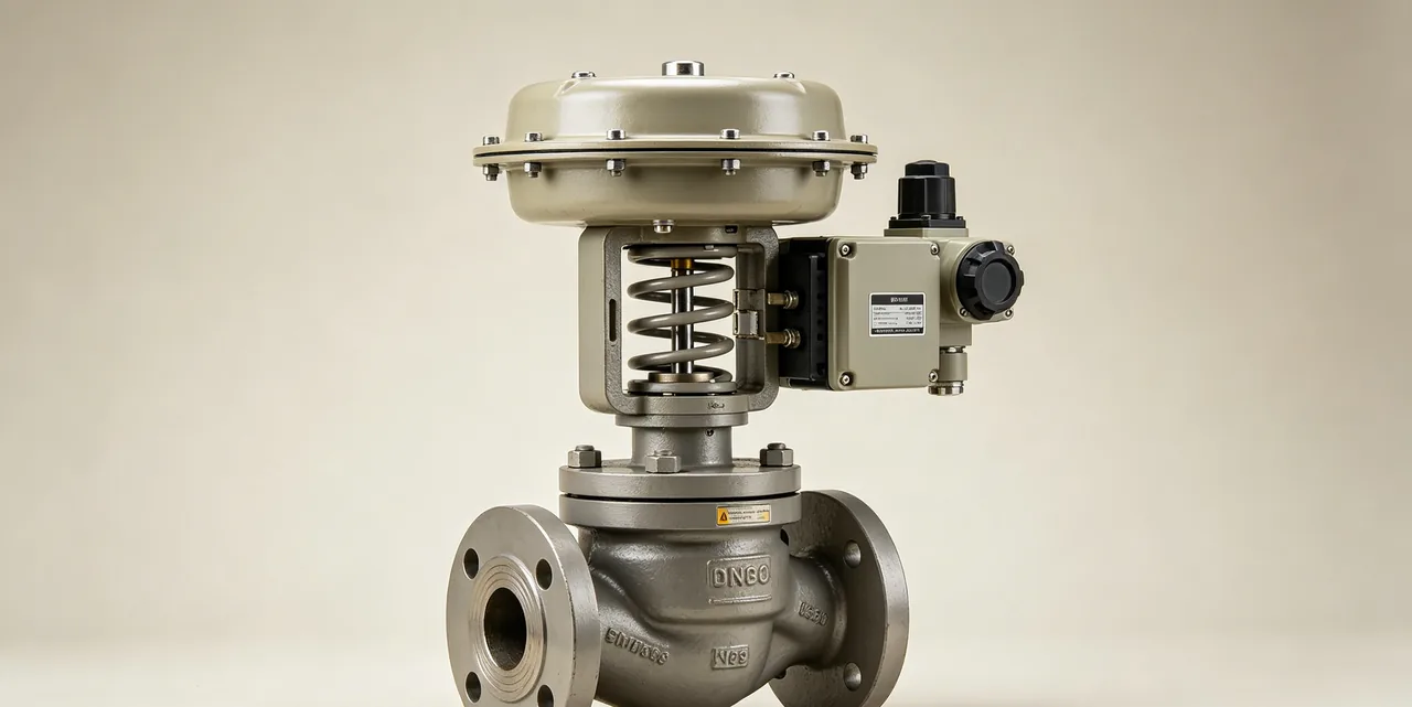
Component Breakdown
A control valve assembly is made up of the valve body and the actuation package:
- Body: The pressure-retaining shell and the most common control-valve body is the globe body, whose internal geometry suits stable throttling. Rotary bodies (segmented ball, eccentric-plug and high-performance butterfly) are used where higher capacity or lower cost is needed.
- Trim: The flow-throttling internals—plug, seat ring and (in cage-guided designs) cage. The trim sets the flow characteristic and capacity, takes the wear and erosion of throttling, and is the part most often re-specified for a given service. Trim materials and hardfacing are chosen for the velocity, erosion and cavitation severity.
- Actuator: The device that supplies positioning force—most commonly a pneumatic spring-and-diaphragm actuator (fail-safe by spring action), or a piston or electric actuator. The actuator is sized for the force needed to stroke the valve against process pressure and friction.
- Positioner: Mounted on the actuator, it ensures the trim reaches the exact position the controller demands, correcting for friction and process load; modern smart positioners also provide diagnostics.
- Bonnet and packing: Guides the stem and seals it to atmosphere; packing selection (graphite, PTFE) follows the temperature and emission requirements.
Trim and Flow Characteristics
The inherent flow characteristic—how flow changes with trim travel at constant pressure drop—is engineered into the trim and is the heart of control-valve selection:
- Linear: flow is directly proportional to travel; used where the valve pressure drop is roughly constant across the operating range, such as level control.
- Equal-percentage: each equal increment of travel changes flow by an equal percentage of the current flow, giving fine control at low flow and coarse control at high flow. It is the most widely specified characteristic because it compensates for the way pipeline pressure drop shifts as flow changes.
- Quick-opening: most of the capacity is reached early in the stroke; suited to on-off and fast-acting duty rather than precise modulation.
Choosing the right characteristic so the installed characteristic stays near-linear across the real operating range is what keeps a loop stable and controllable.
3. Advantages and Disadvantages
Advantages:
- Precise, continuous modulation: holds a process variable accurately at setpoint—something on-off valves cannot do.
- Engineered flow characteristic: trim can be matched to the process to keep the loop stable across its range.
- Integrates with automation: works directly with controllers, positioners and plant control systems, with smart diagnostics available.
- Wide application: available in globe and rotary forms across a broad pressure and size range.
Disadvantages:
- Complexity and cost: more parts (trim, actuator, positioner, instrument air) than an isolation valve, and higher purchase and maintenance cost.
- Requires instrumentation support: needs a control signal, instrument air or power, and tuning to perform.
- Cavitation, flashing and noise risk: throttling can damage trim and generate noise if not correctly sized and specified.
- Not an ideal isolation valve: control valves are generally not relied on for tight shutoff; a separate isolation valve is usually provided.
4. Sizing and Selection
Cv / Kv Sizing

Sizing a control valve means choosing a body and trim whose flow coefficient (Cv, or its metric counterpart Kv) passes the required flow at the available pressure drop across the full operating envelope—minimum, normal and maximum flow. A valve sized only for normal flow will run nearly closed at minimum flow (poor control, seat erosion) and run out of capacity at maximum flow. Correct practice is to size on the required Cv across the whole range and confirm the valve operates in its controllable mid-travel band at normal conditions, as a general engineering rule of thumb the valve should be neither hard against its seat nor wide open at normal flow.
The sizing equations that relate flow, pressure drop, fluid properties and Cv—including the corrections for liquid choked flow, gas and vapour service—are defined in IEC 60534 and are applied with the actual process data rather than assumed coefficients. For the underlying flow-coefficient theory and the calculation walk-through, see Cv Value Explained, and for working through the valve size from process data see Valve Size Calculation.
Avoiding Cavitation, Flashing and Noise
In liquid service, the pressure at the trim's vena contracta can fall below the fluid's vapour pressure. If it recovers above vapour pressure, vapour bubbles collapse violently—cavitation, which erodes trim and generates noise and vibration. If downstream pressure stays below vapour pressure, the fluid stays partly vaporised—flashing, which causes erosion from the high-velocity two-phase flow. In gas and steam service, high trim velocities generate aerodynamic noise. These phenomena are evaluated during sizing using the standard's pressure-recovery and noise-prediction methods, and they are mitigated with anti-cavitation and low-noise trim, staged pressure reduction, and correct material selection—again with the limiting values taken from IEC 60534 and manufacturer data, not assumed.
5. Relevant Standards and Codes
Control valve sizing, testing and rating are governed by recognised standards; the equations, coefficients and limits live in the standards themselves:
- IEC 60534 (Industrial-process control valves): the core standard family covering flow-capacity sizing equations (Cv/Kv), inherent flow characteristics, and aerodynamic noise prediction. It is the primary reference for control-valve sizing.
- ISA standards (e.g. ISA-75 series): control-valve sizing, terminology, capacity testing and inherent flow-characteristic definitions widely used in process industries.
- ASME B16.34: pressure-temperature ratings for the valve body, defining the rated working pressure at the operating temperature.
See the Valve Standards cluster for how these interlock with the wider standards landscape.
6. Related Valve Types and Internal Linking
Most control valves are globe-bodied, and several other valve types serve control duty in modified form—confirm the right choice before specifying:
- Globe Valve — the globe body is the basis of most throttling control valves; this page covers the underlying body in depth.
- Ball Valve and Butterfly Valve — segmented-ball and high-performance butterfly valves serve as rotary control valves where higher capacity or lower cost is needed.
- Industrial Valve Types Overview — the complete comparison of all valve types.
- Cv Value Explained and Valve Size Calculation — the sizing tools that underpin control-valve selection.
Frequently Asked Questions
What are the principles of a control valve?
A control valve is the final control element in a process loop. A sensor measures the process variable, a controller compares it to the setpoint and sends a signal, and the valve actuator moves the trim to throttle flow until the variable matches the setpoint. The valve continuously modulates flow rather than simply opening or closing.
What are the three types of control valves?
By trim flow characteristic, control valves are grouped as linear, equal-percentage and quick-opening. Linear gives flow proportional to travel, equal-percentage gives equal percentage changes in flow per equal travel steps (the most common process choice), and quick-opening delivers most of its flow early in the stroke for on-off-like duty.
What is Cv and Kv in a control valve?
Cv and Kv are flow-coefficient measures of valve capacity. Cv is the US coefficient (US gallons per minute of water at one psi pressure drop) and Kv is the metric equivalent (cubic metres per hour at one bar drop). Both quantify how much flow a valve passes at a given pressure drop and are the basis of valve sizing; the sizing equations are defined in IEC 60534.
What are the two major components of a control valve?
The two major components are the valve body assembly (body plus trim—the plug, seat and cage that actually throttle the flow) and the actuator (which supplies the force to position the trim). A positioner is added to the actuator to ensure the trim reaches the exact position the controller signal demands.