Selecting the wrong valve is one of the most expensive mistakes in process engineering. A poor choice rarely fails on day one—it surfaces months later as seat leakage, accelerated wear, unplanned shutdowns, or a control loop that will not hold its setpoint. Because a valve sits at the intersection of process conditions, materials, and standards, the root cause is almost always upstream: the valve was chosen by habit, by the line size, or by purchase price rather than by a disciplined selection process.
The good news is that the same handful of mistakes account for most field failures, and each has a clear engineering remedy. This guide walks through the valve selection mistakes engineers make most often, explains the failure mechanism behind each, and gives the practice that prevents it. The goal is a way of thinking—define the duty first, then let verified process data drive every downstream decision. For the full step-by-step method, see our guide to selecting an industrial valve.
Mistake 1: Sizing the Valve to the Line, Not the Duty

The most common sizing error is matching the valve to the pipe diameter instead of to the flow it must pass. The two are rarely the same. An oversized control valve is forced to operate close to its seat, where a tiny change in stem position produces a large change in flow—the loop becomes twitchy and hard to tune, and the seat and plug wear quickly from operating in that narrow, high-velocity band. An undersized valve has the opposite problem: it cannot pass the required flow, so it runs wide open, starves the process, and exposes the trim to high velocity and erosion.
Both failures trace to sizing at a single design point. The remedy is to calculate the required flow coefficient across the whole operating envelope—minimum, normal, and maximum flow—and confirm the valve operates in its controllable mid-range at normal conditions. Our explainers on the flow coefficient (Cv) and valve size calculation set out the method. As a general engineering practice, a control valve should approach full flow near the top of its travel and never sit pinned against the seat at normal flow.
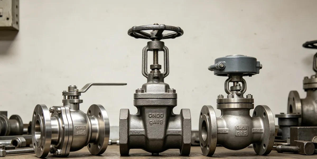
Mistake 2: Using the Wrong Valve Type for the Function
Valves are purpose-built, and the three core duties—isolation, throttling, and backflow prevention—each call for a different design. Treating valves as interchangeable is a reliable way to design in failure. Force a gate valve into a throttling role and the partially open gate vibrates and erodes, because the design was meant to be fully open or fully closed, not to modulate flow. Use a throttling globe valve purely for isolation and you pay an unnecessary pressure-drop penalty for the life of the line.
Match the design to the function before considering brand or price. Quarter-turn ball and butterfly valves suit fast on/off isolation; globe and dedicated control valves are built for throttling and flow regulation; check valves provide automatic backflow protection. Our valve types overview compares the working principles so the function drives the choice rather than whatever happens to be in stock.
Mistake 3: Material Incompatibility with the Service
A valve is only as reliable as its weakest wetted material. A body, trim, or seat that is incompatible with the fluid—through general corrosion, localized pitting, erosion, or chemical attack—degrades rapidly no matter how well the valve is sized or how reputable the maker. Chlorides, abrasive solids, high velocity, temperature, and sour (H2S) content each push the material answer in a different direction, and a default "stainless is fine" assumption is where many failures begin.
Drive material selection from the actual service chemistry rather than convention. Our valve materials guide covers the trade-offs between carbon steel, stainless, duplex, and high alloys. For sour service the controlling document is NACE MR0175/ISO 15156, which constrains material and hardness to resist sulfide stress cracking—see materials for H2S service. Where a material limit applies, specify it by reference to the governing standard, not by assumption.
Mistake 4: Ignoring Pressure-Temperature Ratings
It is easy to fixate on pressure and forget temperature. A valve's maximum allowable working pressure is not a single number—it falls as temperature rises, and the rate of that fall depends on the material. A valve that looks comfortable at ambient pressure can be over its limit at operating temperature, which is a quiet but serious specification error that only reveals itself under upset conditions.
Always check the chosen pressure class against the pressure-temperature rating for the specific material at the actual operating temperature. The governing framework is ASME B16.34, which defines how the rating depends on material group and temperature, complemented by flange ratings in ASME B16.5. Read the value from the standard's tables for your exact material and condition—never carry a rating across from a different material or a lower temperature.
Mistake 5: Overlooking Damaging Flow Phenomena
Sizing for steady flow alone ignores what actually happens inside the valve. The wrong type or size can drive cavitation, flashing, or choked flow—each producing noise, vibration, and aggressive erosion that destroys trim and shortens service life. These effects are not random; they are predictable from the pressure drop and the fluid's properties, yet they are routinely left out of the selection and only discovered after the trim is damaged.
For throttling and control duties, evaluate the pressure-drop regime and the risk of cavitation and flashing as part of selection, and choose trim that manages it—anti-cavitation trim, staged pressure letdown, or a different valve style where needed. The broader valve selection resources cover how pressure-class, trim, and material decisions interact with these phenomena.
Mistake 6: Neglecting Testing and Leakage Class
"Tight shutoff" is not a specification. Without naming the test standard and the acceptable leakage class, two suppliers can each deliver a valve that honestly claims to seal yet performs very differently in service. Leaving this out turns factory acceptance into a negotiation and pushes the discovery of inadequate sealing all the way to commissioning.
State the inspection and test requirement explicitly and reference the applicable leakage criteria—API 598 for valve inspection and testing, with ISO 5208 leakage rate classes where the project requires them. Put the class in the datasheet so the requirement is unambiguous, auditable, and the same for every bidder.
A Best-Practice Selection Checklist
Most selection mistakes disappear when the decision follows a fixed order instead of jumping straight to a product. Work top to bottom and the valve effectively selects itself:
- Define the duty — isolation, throttling, or backflow prevention.
- Capture process conditions — fluid, pressure, temperature, full flow range, solids, and corrosive or sour content.
- Select the valve type that matches the duty and the conditions.
- Size on flow coefficient across minimum, normal, and maximum flow.
- Choose materials from corrosion and service data, by reference to the governing standard.
- Set the pressure class against the pressure-temperature rating at operating temperature.
- Specify testing and leakage class by standard.
Each step constrains the next, so by the time the type, size, material, rating, and test class are fixed, only a small set of valves can satisfy all of them—and the failures described above are never designed in.
Frequently Asked Questions
How do I avoid oversizing a control valve?
Size on the required flow coefficient across the full operating range rather than on the line size, and confirm the valve sits in its controllable mid-travel at normal flow instead of near the seat. See our valve size calculation guide.
Which standard defines valve leakage classes?
Valve inspection and testing is commonly specified to API 598, with ISO 5208 defining the leakage rate classes. Name both the test standard and the acceptable class in the datasheet—see API 598 testing.
What is the first step in valve selection?
Define the duty—isolation, throttling, or backflow prevention—and capture the full process conditions before considering any specific valve. Every later decision depends on that foundation.